Method and apparatus for controlling the length of a carbon nanotube

a carbon nanotube and length technology, applied in the direction of scanning probe techniques, manufacturing tools, instruments, etc., can solve the problems of carbon nanotubes, difficult positional control of catalyst particles, and the length of the tip extending, so as to improve the manufacture efficiency and quality of carbon nanotube sensors

Inactive Publication Date: 2007-05-31
IND TECH RES INST
View PDF11 Cites 8 Cited by
  • Summary
  • Abstract
  • Description
  • Claims
  • Application Information

AI Technical Summary

Benefits of technology

[0009] The primary object of the present invention is to provide a method for controlling the length of the carbon nanotubes so as to control and calibrate the length of the carbon nanotubes, improve the manufacture efficiency and quality of the carbon nanotube sensors, SPM probes or field emitting elements.

Problems solved by technology

Although recent research has focused on the growth of the carbon nanotubes, a number of problems remain in reference to obtaining carbon nanotubes of uniform quality.
Taking the length of the carbon nanotubes as an example, a control of time for growing the carbon nanotubes does not necessarily mean that the length of the tip extending from the carbon nanotubes can be adequately controlled.
This is because the positional control of the catalyst particles is difficult, for example, the catalyst particles may not be formed on the end of the probe tip.
The carbon nanotubes of non-uniform length cause a number of problems in practice.
For example, a lengthy SPM tip tends to be effected by thermal disturbance and results in vibration, though it is instrumental to the probation of a deeper microstructure.
Also, the lengthy carbon nanotube tip tends to cause buckling.
However, all these methods illustrated above need to be achieved through a complex process or expensive apparatus.
Both the complex processing steps and expensive apparatus prevent high-quality carbon nanotubes from popularization in the industry.
Furthermore, even though several complex methods for cutting a single carbon nanotube are disclosed, no simple method or cheap apparatus for mass-producing the carbon nanotubes with uniform length is disclosed.

Method used


Image

  • Method and apparatus for controlling the length of a carbon nanotube
  • Method and apparatus for controlling the length of a carbon nanotube
  • Method and apparatus for controlling the length of a carbon nanotube

Examples


Embodiment Construction

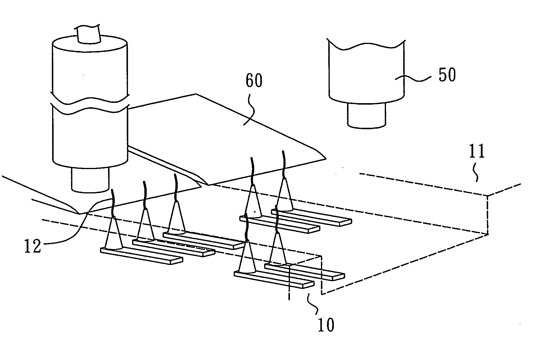
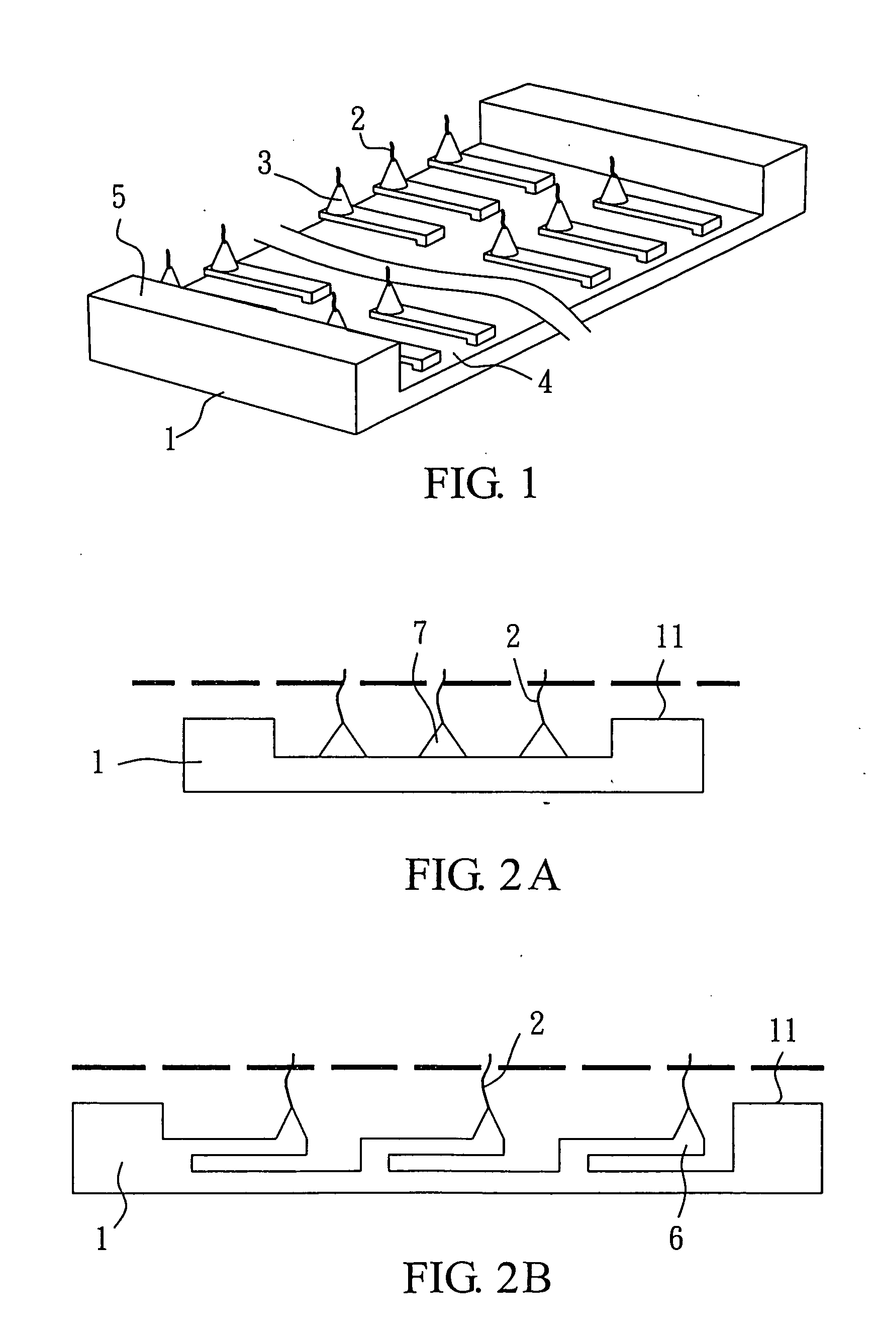
[0020] The array of carbon nanotube probes used in the present invention employs the conventional microelectromechanical technology to form the microstructure thereof. Referring to FIG. 1, an array of probes 3 having carbon nanotubes 2 is formed on a p-type wafer, an n-type wafer, a glass substrate or the like substrate by chemical vapor deposition, plasma-enhanced chemical vapor deposition or field-enhanced chemical vapor deposition. In addition to the carbon nanotubes 2 grown on the end of the cantilever 6, they can be grown on a pyramidal-shaped tip 7 in appropriate embodiments, as shown in FIG. 2. The probes 3 are designed to form on the bottom 4 under a reference level 5. Also, the end of the carbon nanotubes 2 is designed to be grown within a distance from zero to several microns from the reference level 5 below, depending on the application of the probes. A groove-shaped structure is used to reduce the possibility of impact on and damage to the probe end caused by a dischargi...


PUM

PropertyMeasurementUnit
angleaaaaaaaaaa
voltageaaaaaaaaaa
microscopic angleaaaaaaaaaa

Abstract

This invention relates to a method and apparatus for controlling the length of a carbon nanotube, in cooperation with a substrate having at least one reference level on a surface of the substrate on which at least one carbon nanotube is formed, comprising at least one positioning platform for mounting and calibrating the substrate; a discharging electrode mounted on one side of the positioning platform to cut the carbon nanotube wherein the position of the discharging electrode can be calibrated with the positioning platform; a piezoelectric actuator for calibrating the position of the discharging electrode or the height of the discharging electrode relative to the substrate reference level; a position sensor for detection of the height of the substrate; and a voltage pulse supplying means for applying a voltage pulse to the discharging electrode to cut the carbon nanotube.

Description

CROSS-REFERENCE TO RELATED APPLICATION [0001] This application is a division of application Ser. No. 10 / 614,106, filed Jul. 8, 2003.BACKGROUND OF THE INVENTION [0002] 1. Field of the Invention [0003] The present invention relates to a method and apparatus for controlling the length of a carbon nanotube. In particular, the present invention relates to a method and apparatus suitable for modifying the tip of a carbon nanotube probe, a carbon nanotube sensor or a carbon nanotube field emitter. [0004] 2. Description of Related Art [0005] Carbon nanotubes are used widely and an example of such use is as probe tips for scanning probe microscopes (SPMs), measurement of the mass of nano particular or sensors for detection of whether atoms or molecules exist. A probe microscopic cantilever can be made by the current micro-electromechanical technology. An array of probes having carbon nanotube tips can be formed on a p-type wafer, an n-type wafer, a glass substrate or the like substrate by ch...

Claims


Application Information

Patent Timeline
Patent Type & Authority Applications(United States)
IPC IPC(8): B05C11/00C23C16/00C01B31/02G01Q70/12G01Q70/16
CPCB82Y15/00B82Y30/00B82Y35/00B82Y40/00Y10S977/856C01B2202/34G01Q70/12G01Q70/16C01B31/0226C01B32/16
Inventor TAI, HUNG-MINGSHIE, NANG-CHIANCHEN, TSAN-LIN
Owner IND TECH RES INST
Why Eureka
Try Eureka