Gas cooling type vacuum heat treating furnace and cooling gas direction switching device therefor

a vacuum heat treatment furnace and gas direction technology, which is applied in the direction of heat treatment apparatus, muffle furnace, furnace, etc., can solve the problems of high speed cooling, insufficient cooling speed, and inability to heat-treatment, so as to reduce the flow velocity of gas passing, reduce pressure loss, and reduce the effect of surface area

Inactive Publication Date: 2007-05-31
IHI CORP
View PDF10 Cites 18 Cited by
  • Summary
  • Abstract
  • Description
  • Claims
  • Application Information

AI Technical Summary

Benefits of technology

[0035] With the configuration of the sixth aspect of the present invention, of an interior surface A of the furnace body which partitions between the cooling chamber and the gas cooling circulation device, halves are allocated respectively to the suction port and the discharge port of the gas cooling circulation device, and further, haves of each of the suction port and the discharge port are allocated respectively to an upper part and a lower part, thereby the suction opening and the discharge opening may be set to about quarters of the interior area A of the furnace body, respectively. Accordingly, the air passage may have a large area in comparison with the conventional one, thereby it is possible to reduce the flowing velocity of the gas passing through the cooling chamber, resulting in decreased pressure loss.
[0036] Further, since a inside area in the gas cooling furnace is communicated with the suction port of the gas cooling circulation device between the stationary partition plate and the gas cooling and circulating device while only the outside area in the gas cooling furnace is communicated with the discharge port of the gas cooling and circulating device, with a sufficient large gap between the discharge port and the suction port, the gas may flow around onto opposite surfaces even though the opening is made only by a half area, thereby it is possible to effectively use the heat-exchanger in its entirety.

Problems solved by technology

However, a primary stage gas cooling type vacuum heat treating furnace was of a depressurizing and cooling type, and accordingly, its cooling speed was not sufficiently high so as to be disadvantageous.
The high speed circulation gas cooling furnaces disclosed in the non-patent document 1 and the patent document 1 have raised the following problems since the heating and cooling have been carried out at one and the same position: (1) The heater and the furnace body which are at a high temperature after completion of heating are both cooled simultaneously with cooling of the article to be heat-treated, and accordingly, high speed cooling for the article to be heat-treated cannot be made; (2) The article to be heat-treated is surrounded by the heater and the furnace body, and accordingly, cooling gas cannot be uniformly fed thereto during cooling; (3) Even though the gas cooling is made alternately upward and downward, there are no means for rectifying both upward gas and downward gas so as to flow in uniform directions at uniform speeds, and accordingly, it has been difficult to reduce distortion of an article to be heat-treated in its entirely.
However, in the case of using the upper and lower damper units as a cooling gas direction change-over mechanism, there have been raised the following problems: (4) The damper units cause considerable variation in load exerted by a pressure of gas flowing at a high speed, depending upon an open and a close position thereof.
Thus, in the case of high pressure gas, it is difficult due to affection by the pressure of air to smoothly operate such a damper system.
Thus, upon switching of a plurality of upper and lower drive devices, it is difficult to balances opening areas in order, resulting in a difference in opening area between a suction port and a discharge port and considerable variation in the difference, and accordingly, the quantity of cooling gas varies so as to cause stable gas cooling to be difficult.
(6) There are presented a plurality of upper and lower damper units, and accordingly, a plurality of drive devices therefor are required, resulting in a complicated configuration.

Method used


Image

  • Gas cooling type vacuum heat treating furnace and cooling gas direction switching device therefor
  • Gas cooling type vacuum heat treating furnace and cooling gas direction switching device therefor
  • Gas cooling type vacuum heat treating furnace and cooling gas direction switching device therefor

Examples


first embodiment

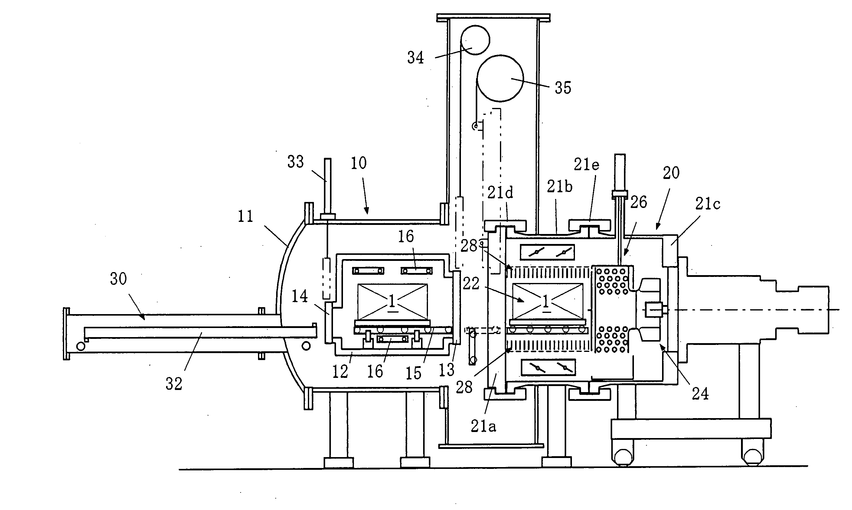
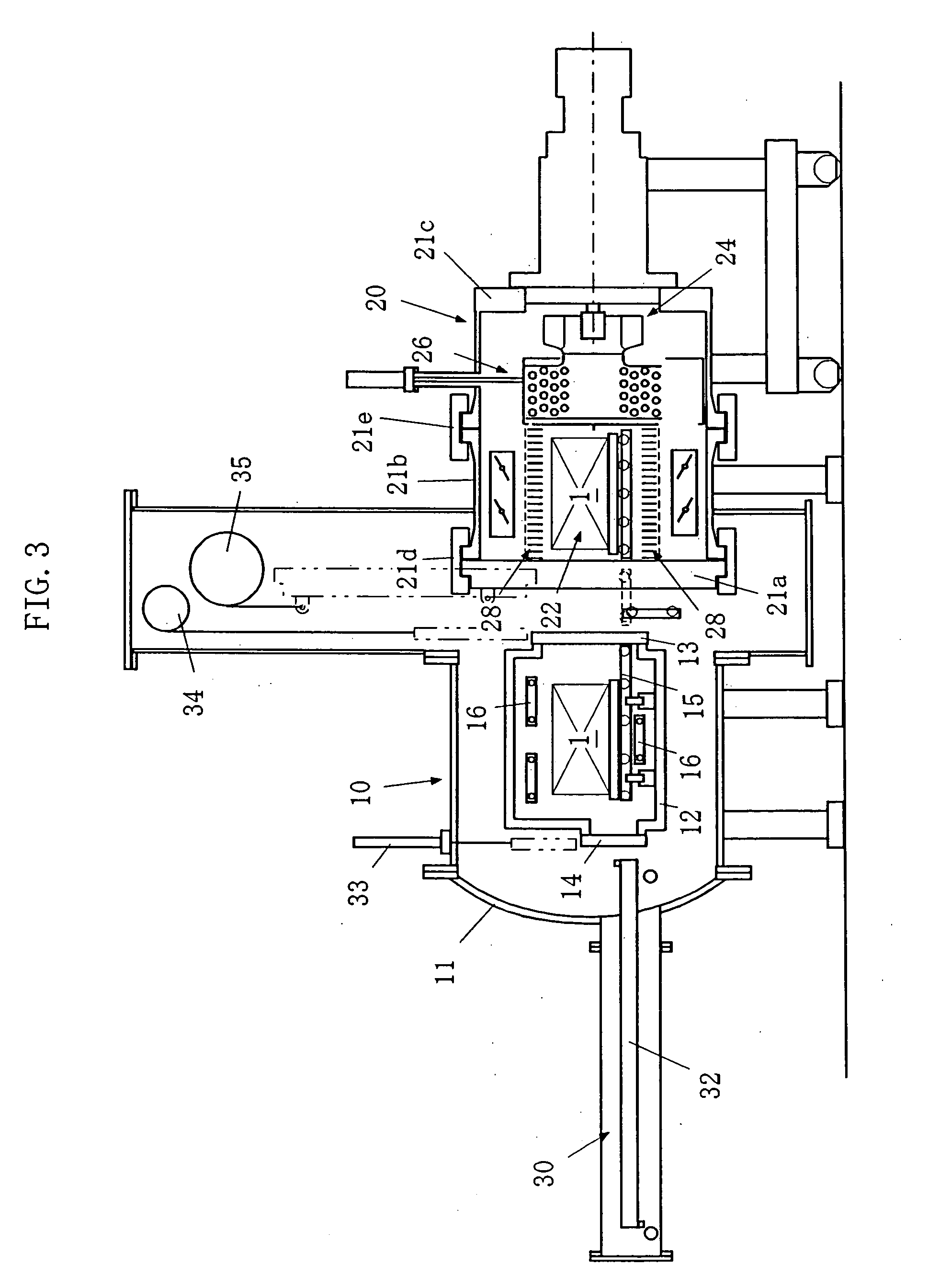
[0073]FIG. 6 shows an entire configuration of a vacuum heat-treating furnace incorporating the cooling gas direction switching device according to the present invention. The vacuum heat-treating furnace is of a multi-chamber type, comprising a vacuum heating furnace 10, a gas cooling furnace and a shifter 30, the vacuum heating furnace 10 and the shifter 30 have configurations similar to those shown in FIG. 3 as stated above.

[0074]FIG. 7 is a partial enlarged view of FIG. 6. Referring to FIGS. 6 and 7, the cooling furnace 20 incorporates a vacuum vessel 21, a cooling chamber 22, a gas cooling and circulating device 24, a cooling gas direction switching device 40, straighteners 28, and auxiliary distribution mechanisms 29. The vacuum vessel 21, the cooling chamber 22, the straighteners 28 and the auxiliary distribution mechanism 29 have configurations similar to those shown in FIGS. 4 and 5 as stated above.

[0075] The gas cooling and circulating device 24 is composed of a cooling fan...

second embodiment

[0092]FIGS. 10A and 10B are sectional views which show a cooling gas direction switching device in the present invention, similar to FIGS. 9A and 9B. FIG. 10A is a sectional view along line C-C, that is, a front view illustrating the rotary partition plate 44 while FIG. 10B is a sectional view from which the rotary partition wall is removed, that is, a front view illustrating the stationary partition plate 42.

[0093] In this second embodiment, the cooling gas direction switching device is capable of coping with both vertically flowing the gas (vertical flow) and horizontally flowing the gas (horizontal flow).

[0094] That is, in this example, the suction opening 44a has a substantially quarter circle shape while the discharge opening 44b has a substantially quarter sector shape, which are arranged on opposite sides of a horizontal axis (the horizontal partition plate 22c as stated above)

[0095] In this embodiment, when the gas vertically flows in the cooling chamber 22, the suction op...


PUM

PropertyMeasurementUnit
Angleaaaaaaaaaa
velocity distributionaaaaaaaaaa
flow resistanceaaaaaaaaaa

Abstract

A gas cooling type vacuum heat-treating furnace according to the present invention, includes a gas cooling furnace comprising a cooling chamber in which an article to be heat-treated is stationarily set, and defining therein a gas passage in a vertical direction, a gas cooling and circulating device for cooling and circulating gas flowing in the cooling chamber, a gas direction switching device for alternately changing over directions of gas vertically passing through the cooling chamber, and upper and lower straighteners blocking upper and lower ends of the cooling chamber, for causing a velocity distribution of the gas to be uniform.

Description

BACKGROUND OF THE INVENTION [0001] 1. Technical Field of the Invention [0002] The present invention relates to a gas cooling type vacuum heat treating furnace and a cooling gas direction switching device therefor. [0003] 2. Description of the Related Art [0004] A vacuum heat treating furnace is the one in which inert gas or the like is refilled after depressurization therein in order to carry out heat-treatment of an article. Since the vacuum heat treating furnace may completely remove moisture or the like sticking to the interior of the furnace and to the treated article after heating, by depressurizing again the furnace after evaporation of the moisture or the like, and refilling the inert gas or the like thereinto, there may be exhibited such an merit that heat-treatment may be made without coloring by moisture (the so-called bright heat-treatment). [0005] Further, a gas cooling type vacuum heat treating furnace may exhibit various merits such as capability of performing bright h...

Claims


Application Information

Patent Timeline
Patent Type & Authority Applications(United States)
IPC IPC(8): F27D15/02F27B5/16F27B17/00F27D7/04F27D9/00
CPCC21D9/0062F27B5/16F27B17/0033F27D7/04C21D1/773F27D9/00
Inventor KATSUMATA, KAZUHIKO
Owner IHI CORP
Why Eureka
Try Eureka