Toner manufacturing method

a manufacturing method and technology for toners, applied in the field of toner manufacturing methods, can solve the problems of poor powder fluidity, irregular particle shape, and significant deterioration of powder fluidity, and achieve the effect of uneven charging capability, lack of uniformity in characteristics, and efficient granulation of resin kneaded products

Inactive Publication Date: 2007-06-07
SHARP KK
View PDF6 Cites 12 Cited by
  • Summary
  • Abstract
  • Description
  • Claims
  • Application Information

AI Technical Summary

Benefits of technology

[0044] According to the invention, the dispersant contained in the dispersant-containing aqueous medium is made of a substance which is soluble in water. Therefore, the dispersant is contained in a water-dissolved state in the admixture of the resin kneaded product and the dispersant-containing aqueous medium. In this case, in contrast to the case where the dispersant is contained in a solid state in the admixture, it is possible to prevent generation of air bubbles from the dispersant, and thereby achieve efficient granulation of the resin kneaded product. As another advantage, since the dispersant can be prevented from remaining in the resultant toner particles, it is possible to obtain with ease a toner free from, for example, uneven charging capability and thus lack of uniformity in its characteristics.

Problems solved by technology

In the case of adopting the pulverization method, however, the smaller is the particle diameter of the toner obtained, the more likely it is that the particles will be irregular-shaped.
This gives rise to a problem of a significant deterioration in powder fluidity.
Such a toner as has poor powder fluidity cannot be supplied to the surface of the photoreceptor with stability in a development process, in consequence whereof there results degradation in image quality.
Moreover, the toner obtained by the pulverization method is liable to suffer from uneven charging capability because of its relatively wide range of particle size distribution.
If image formation is carried out by using such a toner as has uneven charging capability, at the time of transferring a toner image onto a transference material, part of the toner cannot be transferred onto the transference material properly due to lack of charge amounts, thus causing an undesirable decrease in image density or the like problem.
Occurrence of uneven charging capability in the toner obtained by the pulverization method cannot be prevented without the necessity of carrying out classification after granulation is completed through a pulverization process to narrow the particle size distribution range.
However, the classification leads to low toner yield and thus gives rise to another problem of high cost of manufacturing.
As described hereinabove, the pulverization method presents various problems.
However, the above stated methods (i) through (v) present the following problems.
Therefore, a resin material which is usable as a binder resin is limited to vinyl polymer that can be produced by radical polymerization.
Another problem associated with the polymerization method is occurrence of uneven charging capability in toner particles resulting from residual binder resin monomer, polymerization initiator, and suspension stabilizer, and so forth remaining within the toner particles.
Although occurrence of uneven charging capability cannot be prevented without the necessity of removing such residues, it is extremely difficult to remove the monomer, polymerization initiator, and suspension stabilizer, and so forth incorporated inside the toner particles.
Moreover, according to the emulsification polymerization-based agglomeration method (ii), since a toner is produced by melting the agglomerated particles of the binder resin, the colorant, and so forth with application of heat, there arises a problem that toner particles having uniform composition cannot be formed with stability.
Another problem associated with the methods (iii) through (v) is that a resin material which is usable as the binder resin is limited to a water-dispersible resin having a dissociation group or an organic solvent-soluble resin.
At this time, depending upon a temperature at which the aqueous medium is heated, the melt viscosity of the resin kneaded product may become so low that various components contained in the resin kneaded product, such as a colorant, a release agent, and a charge controlling agent are liable to agglomerate.
This could lead to low dispersibility.
Moreover, the components dispersed in the resin kneaded product such as the colorant may be separated from the resin kneaded product, which could result in deviation of the composition of a toner to be obtained from the intended composition.
Variation in the dispersibility or composition of the components contained in the resin kneaded product gives rise to a problem that the desired characteristics cannot be attained.
However, the lower is the heating temperature for the aqueous medium, the more likely it is that the resin kneaded product will not be melted easily.
This increases the possibility of a failure of granulation.
Furthermore, even if granulation can be achieved somehow or other, it is difficult to obtain a volumetric average particle diameter ranging from approximately 3 μm to 8 μm, which is suitable for an electrostatic charge image developing toner, and also it is inevitable that the particle size distribution becomes broad.

Method used


Image

  • Toner manufacturing method
  • Toner manufacturing method
  • Toner manufacturing method

Examples


example 1

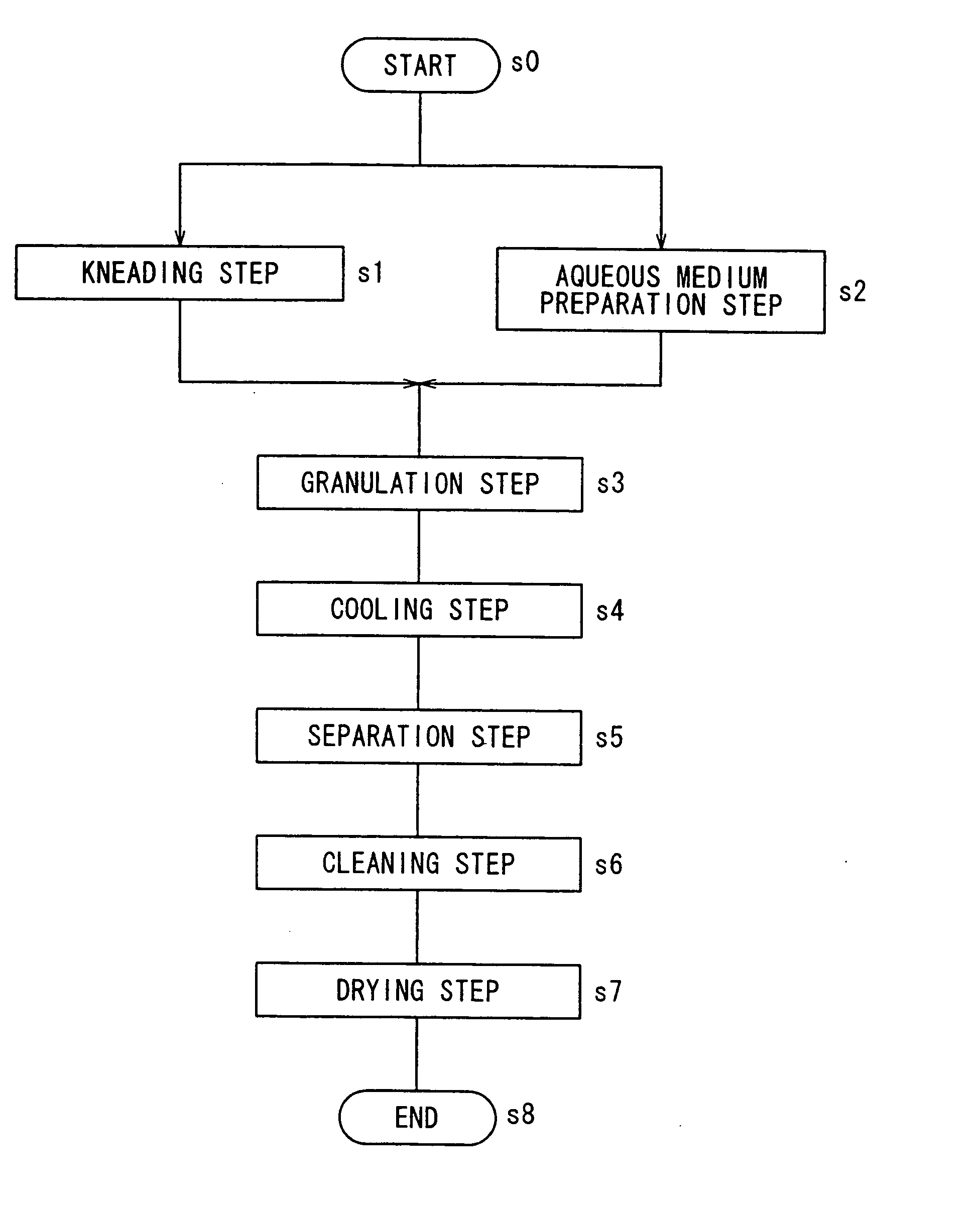
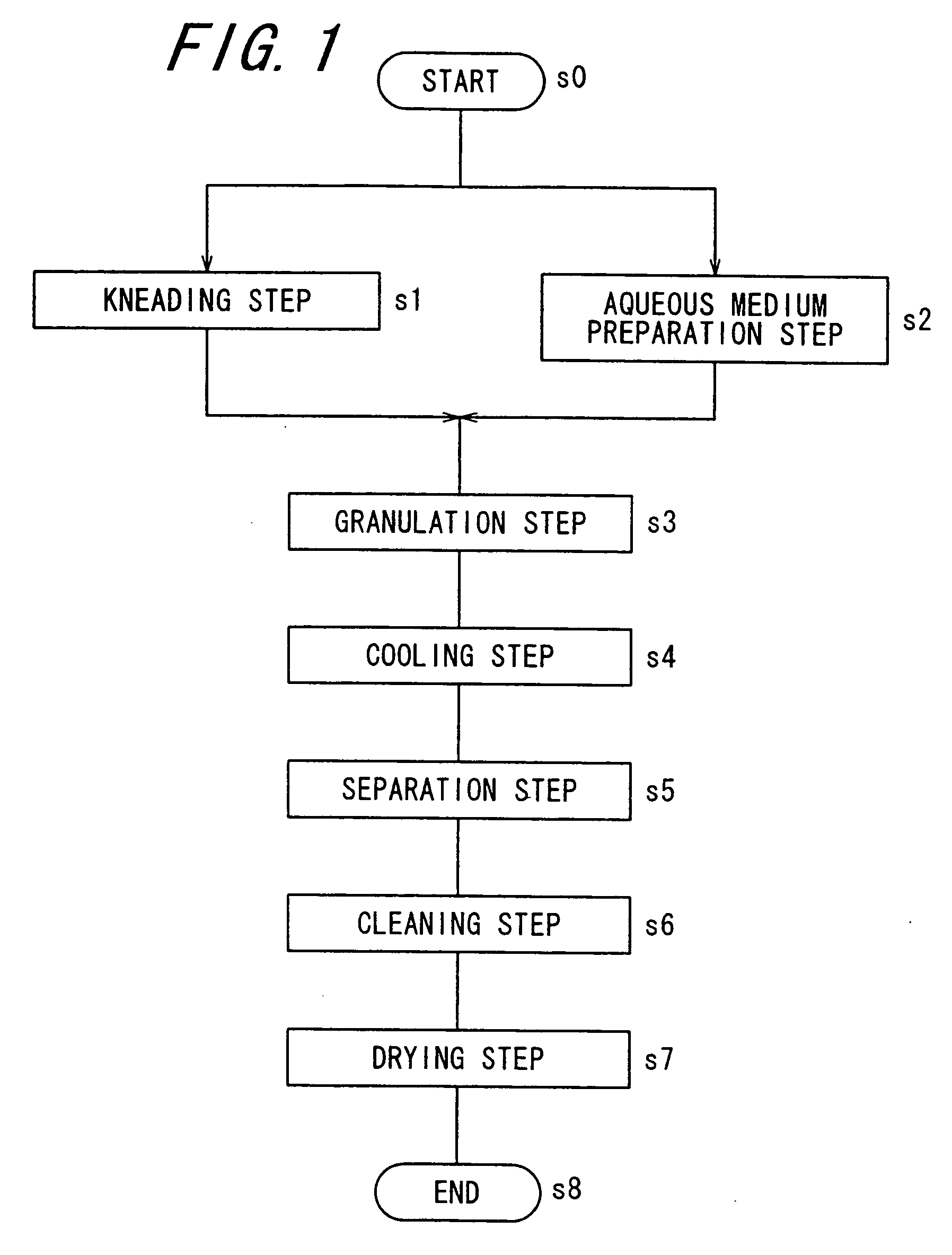
[0168] [Kneading Step]

[0169] There were prepared: 890 parts of polyester resin A (having glass transition temperature of 56.7° C., peak top molecular weight of 12500, Mw / Mn of 2.5, acid value of 16, softening temperature of 102° C., and THF-insoluble component of 0%) for use as a binder resin; 50 parts of C.I. pigment blue 15:3 Blue No. 26 (trade name) manufactured by Dainichi seika Color & Chemicals Mfg. Co., Ltd. for use as a colorant; 10 parts of a charge controlling agent: BONTRON E 84 (trade name) manufactured by Orient Chemical Industries, Ltd.; and 50 parts of wax: TOWAX 161 (trade name) manufactured by To a Kasei Co., Ltd. for use as a release agent. These constituent components have been mixed and dispersed for 3 minutes by using a mixer: Henschel Mixer (trade name) manufactured by Mitsui Mining Co., Ltd. to obtain a raw material admixture. Next, the obtained raw material admixture was melt-kneaded by using a twin-screw extruder: PCM-30 (trade name) manufactured by Ikegai C...

example 2

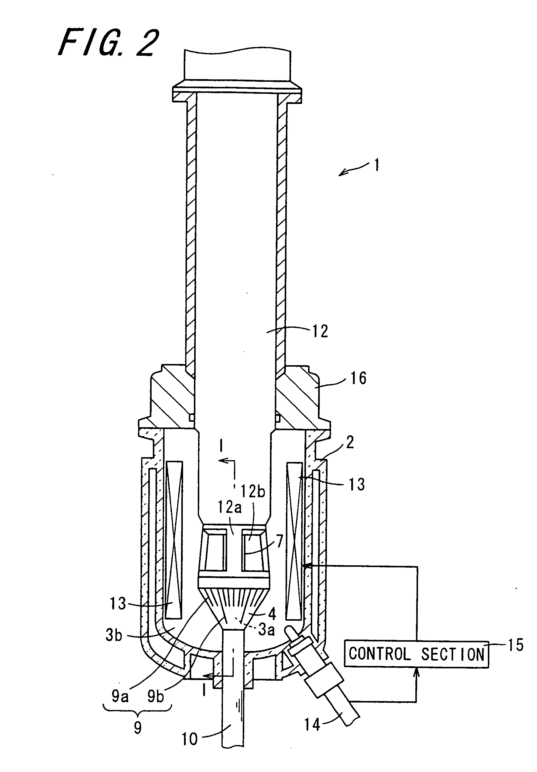
[0178] As Example 2, a toner having a volumetric average particle diameter (D50) of 6.1 μm and a variable coefficient (CV) of 26 was formed by carrying out the same operations as those in Example 1 except that, in the granulation step, after the granulation temperature has been reached, the number of rotation of the rotor 5 was adjusted to 12000 rpm (12000 rotations / min.) and the number of rotation of the screen 4 was adjusted to 10800 rpm (10800 rotations / min.) (the ratio of the rpm of the screen 4 to the rpm of the rotor 5 stood at 0.90).

example 3

[0179] As Example 3, a toner having a volumetric average particle diameter (D50) of 4.3 μm and a variable coefficient (CV) of 22 was formed by carrying out the same operations as those in Example 1 except that, in the granulation step, after the granulation temperature has been reached, the number of rotation of the rotor 5 was adjusted to 20000 rpm (20000 rotations / min.) and the number of rotation of the screen 4 was adjusted to 18000 rpm (18000 rotations / min.) (the ratio of the rpm of the screen 4 to the rpm of the rotor 5 is 0.90).


PUM


Abstract

A toner manufacturing method that allows production of toner having desired characteristics with stability in accordance with fusion emulsification technique for obtaining a toner by granulating a resin kneaded product while dispersing it in an aqueous medium. A resin kneaded product containing at least a binder resin and a colorant is mixed with a dispersant/water-containing aqueous medium. The resultant admixture is stirred by an stirring apparatus including a screen with an admixture discharge hole disposed internally of a vessel and a rotor disposed in an stirring space created by the screen.

Description

CROSS-REFERENCE TO RELATED APPLICATION [0001] This application claims priority to Japanese Patent Application No. JP 2005-349496, which was filed on Dec. 2, 2005, the contents of which, are incorporated herein by reference, in their entirety. BACKGROUND OF THE INVENTION [0002] 1. Field of the Invention [0003] The present invention relates to a method for manufacturing a toner designed for use in development of an electrostatic charge image or the like during the course of image formation effected by means of electrophotography or otherwise. [0004] 2. Description of the Related Art [0005] In an electrophotographic image forming apparatus for forming images by electrophotographic method, image formation is accomplished in the following manner, for example. After an electrostatic charge image is formed on a surface of an electrophotographic photoreceptor (hereafter also referred to simply as “the photoreceptor”) by various apparatuses, the electrostatic charge image is developed into a...

Claims


Application Information

Patent Timeline
Patent Type & Authority Applications(United States)
IPC IPC(8): G03G9/08
CPCG03G9/0804G03G9/0808G03G9/0815
Inventor ARIYOSHI, SATORUKAWASE, YOSHITAKAKIKAWA, KEIICHIMATSUMOTO, KATSURU
Owner SHARP KK
Why Eureka
Try Eureka