
Speaker, speaker-use diaphragm, dust cap, production methods and production devices for them

a technology for speakers and diaphragms, applied in the direction of transducer diaphragms, electromechanical transducers, instruments, etc., can solve the problems of poor moisture resistance reliability and strength, inability to meet the demand for high performance, and papermaking requires a large number of processes, so as to achieve excellent moisture and water resistance reliability, performance and audio quality adjustment, strength and external appearan

Inactive Publication Date: 2007-06-14
PANASONIC CORP
View PDF6 Cites 32 Cited by
  • Summary
  • Abstract
  • Description
  • Claims
  • Application Information

AI Technical Summary

Benefits of technology

[0020] The diaphragm and dust cap of the present invention are formed by injection molding a material containing at least a resin material and a fiber material. As a result, the diaphragm and dust cap can combine the advantages of both paper and resin. More specifically, the diaphragm and the dust cap can have a large degree of freedom in setting physical properties as the advantage of paper, and be excellent in moisture resistance reliability, strength, external appearance, productivity and dimension stability as the advantages of resin. This achieves the creation of characteristics and sound of the speaker by making use of the physical properties of both paper and resin, which have not been achieved conventionally.
[0022] Furthermore, different color combinations of materials used in the diaphragm or the dust cap can allow the speaker to be designed diversely. In addition, the diaphragm or the dust cap can be manufactured in infinite color combinations so as to make the speaker meet the demand for design in addition to the demands for the creation of performance and sound.
[0024] In the manufacturing method, fibrous resin and filler are wet mixed to form a primary composite material in a process, while granular resin is formed by grinding the resin in a separate process. The primary composite material and the granular resin are complexed again in a second complexing process, which substitutes the resin for moisture to make them well blended, thereby drawing out the advantages of both the resin and the filler.
[0026] In short, the manufacturing method substitutes the resin for moisture to make the resin and the filler well blended, thereby drawing out the advantages of both the resin and the filler. As a result, a speaker using this diaphragm can have performance and audio quality adjusted in a wide range, and be excellent in moisture and water resistance reliability, strength and external appearance.
[0027] Furthermore, the method and facility of the present invention for manufacturing a diaphragm can achieve the physical properties of a paper diaphragm with high productivity and stability, which used to be obtained through a long paper-making process.
[0028] The present invention, which provides a method and facility for manufacturing a speaker diaphragm or a dust cap combining the advantages of both the resin and the filler, has an extremely high industrial value.

Problems solved by technology

However, they have their own problems and cannot meet the demand for high performance.
On the other hand, they are poor in moisture resistance reliability and strength, which are features unique to paper.
As another disadvantage of paper diaphragms, the paper making requires a large number of processes.
In contrast, resin diaphragms are excellent in moisture resistance reliability, strength, external appearance and productivity; however, they only have uniform physical properties unique to resin.
Resin diaphragms, however, can allow the speaker to adjust performance and audio quality only within the range of the material properties of resins, so that the speaker can create nothing but standardized sound only.
This makes it impossible for the speaker to create diverse sound or to have its characteristics adjusted in a wider range so as to meet the market demand.
When a resin is mixed with pulp, however, the pulp cannot be dispersed evenly in the resin.
As a result, the speaker cannot have the desired performance and audio quality.

Method used


Image

  • Speaker, speaker-use diaphragm, dust cap, production methods and production devices for them
  • Speaker, speaker-use diaphragm, dust cap, production methods and production devices for them
  • Speaker, speaker-use diaphragm, dust cap, production methods and production devices for them

Examples


first exemplary embodiment

[0080] A first embodiment will describe a speaker diaphragm of the present invention.

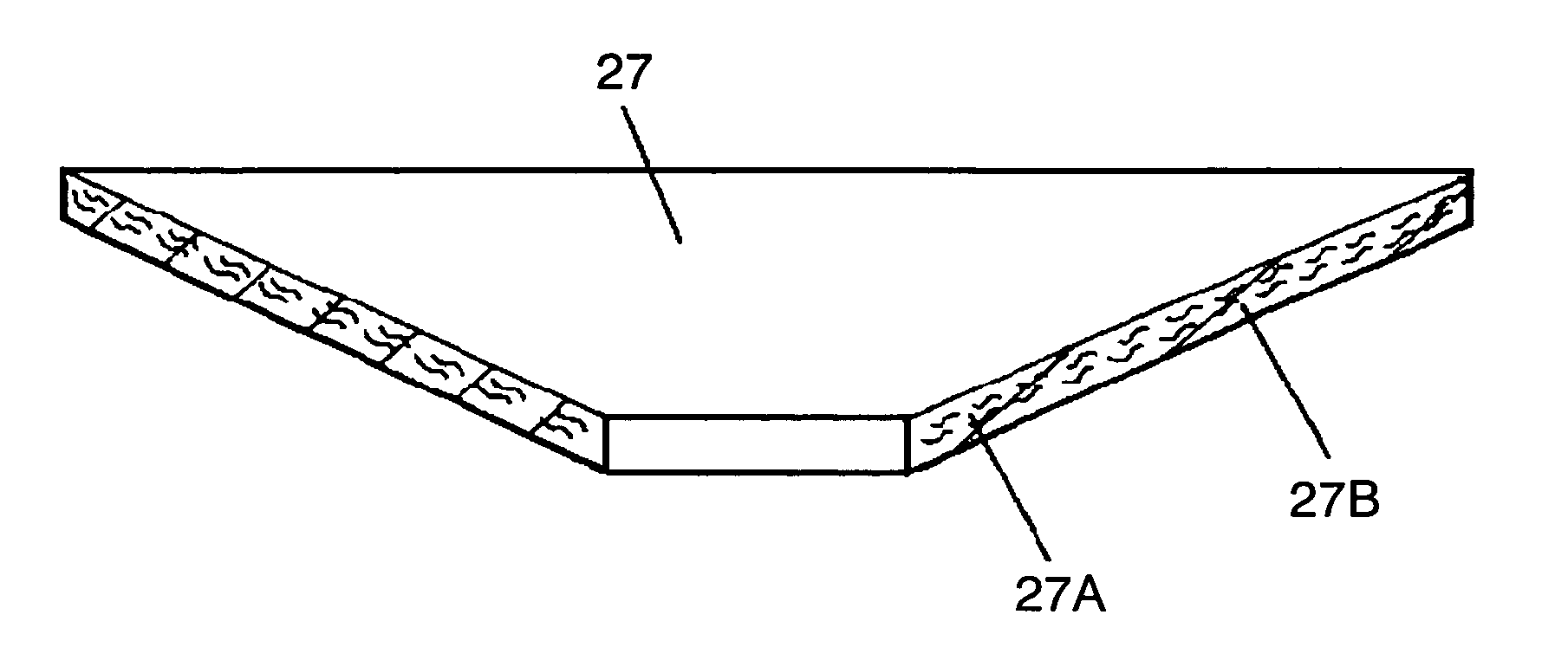
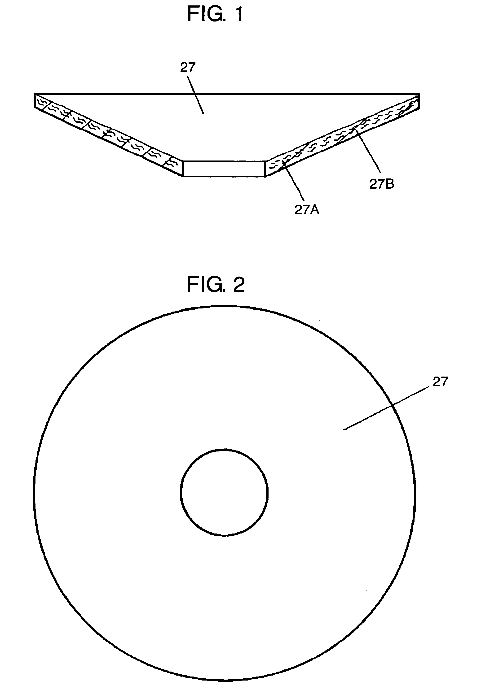
[0081]FIGS. 1 and 2 show the diaphragm of the embodiment of the present invention. Diaphragm 27 is formed by injection molding a material containing resin material 27A and pulp 27B. As resin material 27A of diaphragm 27, a crystalline or amorphous olefin resin is used.

[0082] Using an olefin resin can provide excellent formability. Furthermore, choosing between a crystalline resin material and an amorphous resin material depending on application can allow the diaphragm to have its optimum physical properties.

[0083] The following is a description of the case where resin material 27A is made of polypropylene. Polypropylene is easily available and easily injection-molded. Note that the present invention can use various types of resin materials besides polypropylene, depending on the desired properties. For example, when the diaphragm is required to be highly resistant to heat and solvent, the require...

second exemplary embodiment

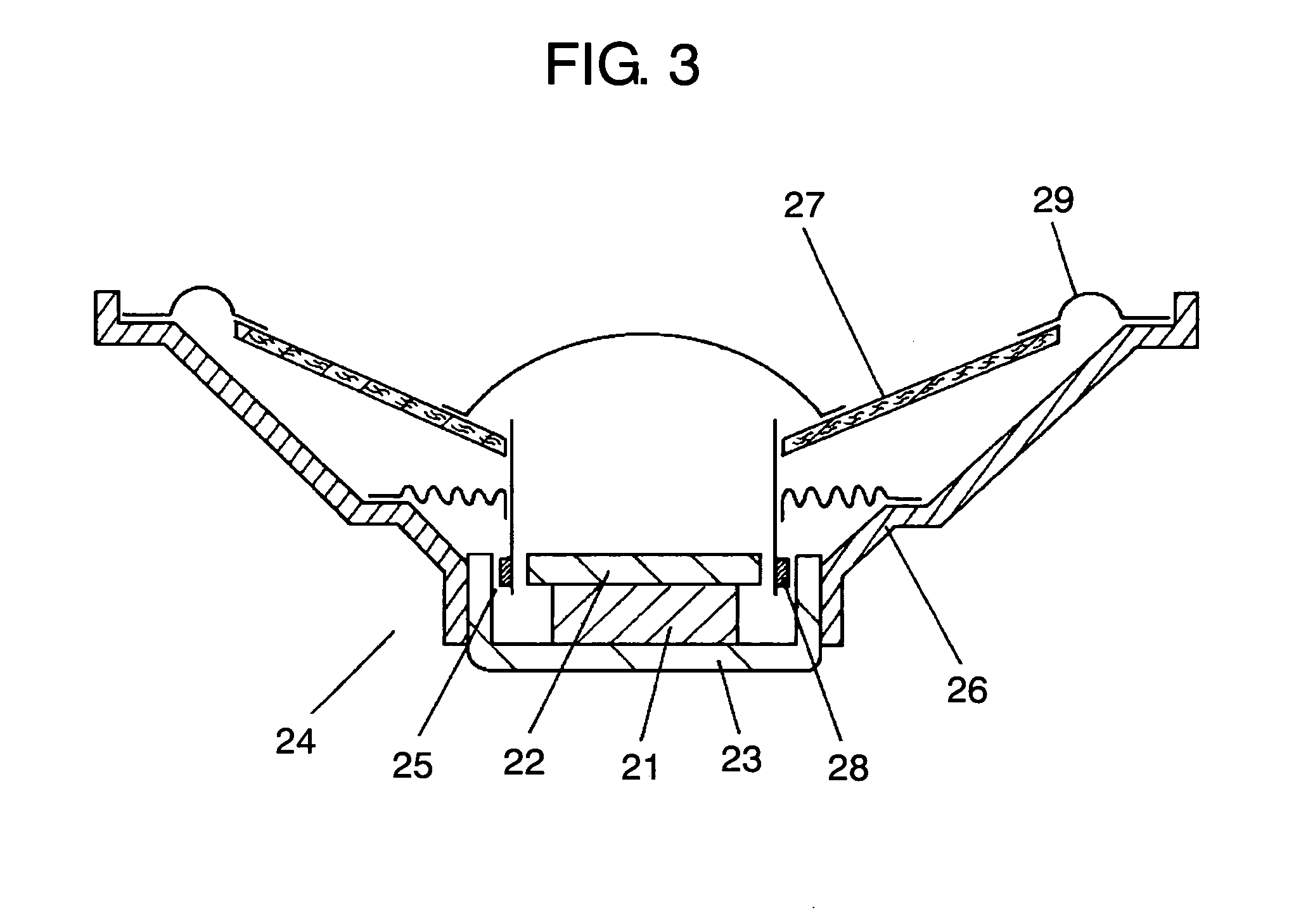
[0103]FIG. 3 is a cross sectional view of a speaker of an embodiment of the present invention. As shown in FIG. 3, the speaker has internal magnet-type magnetic circuit 24 in which magnetized magnet 21 is sandwiched between upper plate 22 and yoke 23.

[0104] Yoke 23 of magnetic circuit 24 is attached to frame 26. Frame 26 is combined with diaphragm 27 of the first embodiment by bonding its periphery to the circumference of diaphragm 27 via edge 29. Furthermore, voice coil 28 is connected with the center of diaphragm 27 at one end thereof and is fit into magnetic gap 25 at the other end thereof.

[0105] Although the speaker of the second embodiment has internal magnet-type magnetic circuit 24, the present invention is not limited to this type and can be applied to speakers having an external magnet-type magnetic circuit. The present invention can further be applied to mini speakers used in mobile phones and the like in which diaphragm 27 and edge 29 are integrated.

[0106] Using the di...

third exemplary embodiment

[0109]FIG. 4 is an external view of an audio mini component system which is electronic equipment of an embodiment of the present invention. As shown in FIG. 4, speaker 30 of the second embodiment of the present invention is integrated into enclosure 41 to form a speaker system. Audio mini component system 44 as electronic equipment includes amplifier 42 for amplifying electric signals to be inputted to speaker 30, and player 43 for outputting a source to be inputted to amplifier 42.

[0110] Using the diaphragm of the present invention can achieve a speaker system, as the electronic equipment, capable of producing performance, sound and design with high precision by using the advantages of both a paper diaphragm and a resin diaphragm, which have not been achieved by conventional diaphragms.


PUM


Abstract

A speaker diaphragm or a dust cap formed by injection molding a mixture at least containing a resin material and a fiber material. The speaker diaphragm or the dust cap combines the advantages of both a paper diaphragm and a resin diaphragm. The advantage of a paper diaphragm is a large degree of freedom in setting physical properties. The advantages of a resin diaphragm are being excellent in moisture resistance reliability, strength, external appearance, productivity and dimension stability.

Description

TECHNICAL FIELD [0001] The present invention relates to a speaker diaphragm and a dust cap which are used in various types of audio and video equipment. BACKGROUND ART [0002]FIG. 9 shows a conventional speaker diaphragm formed by resin injection molding. FIG. 10 shows a conventional dust cap. Speaker diaphragm 207 and dust cap 209 shown respectively in FIGS. 9 and 10 are formed by melting pellets of polypropylene or other resins and then by injection molding the melted resin in their respective molds. The prior art will be described as follows by focusing on diaphragms. [0003] As a material for injection molding, a polymer material such as polypropylene is commonly used on its own. Besides, a blend-type material containing different types of resins is often used to adjust the physical properties of the diaphragm or the dust cap, thereby adjusting the performance and audio quality of the speaker. It is also possible to add reinforcement such as mica to the molding material in order t...

Claims


Application Information

Patent Timeline
Patent Type & Authority Applications(United States)
IPC IPC(8): H04R7/00H04R7/02H04R7/12H04R31/00
CPCH04R7/12H04R31/003H04R2231/001H04R2307/021H04R2307/025H04R2307/029
Inventor OKAZAKI, MASATOSHISUZUMURA, MASAKIMIZONE, SHINYAKAJIHARA, YOSHIMICHINISHIMURA, KAZUAKISUMIYAMA, MASAHIDE
Owner PANASONIC CORP
Learn More