Cold-cathode tube lighting device for use in a plurality of cold-cathode tubes lit by two low-impedance power sources

a cold-cathode tube and lighting device technology, which is applied in the direction of dc-ac conversion without reversal, process and machine control, instruments, etc., can solve the problems of imbalance in increase in leakage current between the tube wall and the external, and impair the uniformity of the tube current in the longitudinal direction, so as to achieve the effect of increasing the uniformity of the luminance in the longitudinal direction of each cold-cathod

Inactive Publication Date: 2007-06-14
PANASONIC CORP
View PDF18 Cites 6 Cited by
  • Summary
  • Abstract
  • Description
  • Claims
  • Application Information

AI Technical Summary

Benefits of technology

[0053] Unlike the device according to the prior art, the above-mentioned cold-cathode tube lighting device according to the present invention includes a plurality of ballast capacitors, at least one of which is connected to each of a plurality of cold-cathode tubes, and a common low-impedance power source so as to uniformly lighten the plurality of cold-cathode tubes using the common power source. Further, the wires between the power source and the ballast capacitors may be long, and may be significantly different for each ballast capacitor, and therefore the layout of the wiring is high in flexibility. Accordingly, the downsizing of the whole device is realized more easily than that of the device according to the prior art.
[0054] Further, in the cold-cathode tube lighting device according to the present invention, the two low-impedance power sources separately change the electrode potentials at both ends of each of the plurality of cold-cathode tubes. In this case, the frequencies of the outputs from the two low-impedance power sources are set to be equal to each other. On the other hand, amplitudes of the outputs from the two low-impedance power source are set independently. In addition, the phase correction circuit adjusts the phase difference between the outputs from the two low-impedance power sources. Thus, even if a circuit configuration of a part between one low-impedance power source and the cold-cathode tubes, and a circuit configuration of a part between the other low-impedance power source and the cold-cathode tubes are greatly different from each other, the electrode potentials at both ends of each cold-cathode tube are maintained asymmetrically with respect to the ground potential. Accordingly, the uniformity of the luminance in the longitudinal direction of each cold-cathode tube is further raised.
[0055] Preferably, in the cold-cathode tube lighting device according to the present invention, the ballast is connected only to between the first low-impedance power source and the electrode at one end of each cold-cathode tube. Thus, only by using the ballasts of the same number as the cold-cathode tubes, the uniformity of the luminance in the longitudinal direction of each cold-cathode tube can be raised.
[0056] Further, when two low-impedance power sources are used as described above, the withstand voltages of the circuit elements included in the power sources are reduced by half compared to those when one low-impedance power source is used.
[0057] The downsizing of the cold-cathode tube lighting device according to the present invention is further easily realized.
[0058] For example, when the cold-cathode tube lighting device according to the present invention is used as the back light of the liquid crystal display, the display can be easily made thin.

Problems solved by technology

Accordingly, when the stray capacitance between the tube wall and the external part is excessive, the leakage current flowing between the tube wall and the external increases excessively particularly near above-mentioned the other electrode.
Particularly when the code cathode tube FL is long, the excessive increase of the leakage current may impair the uniformity of the tube current in the longitudinal direction.
As a result, an imbalance in luminance may occur in the longitudinal direction of the cold-cathode tube FL.

Method used


Image

  • Cold-cathode tube lighting device for use in a plurality of cold-cathode tubes lit by two low-impedance power sources
  • Cold-cathode tube lighting device for use in a plurality of cold-cathode tubes lit by two low-impedance power sources
  • Cold-cathode tube lighting device for use in a plurality of cold-cathode tubes lit by two low-impedance power sources

Examples


first preferred embodiment

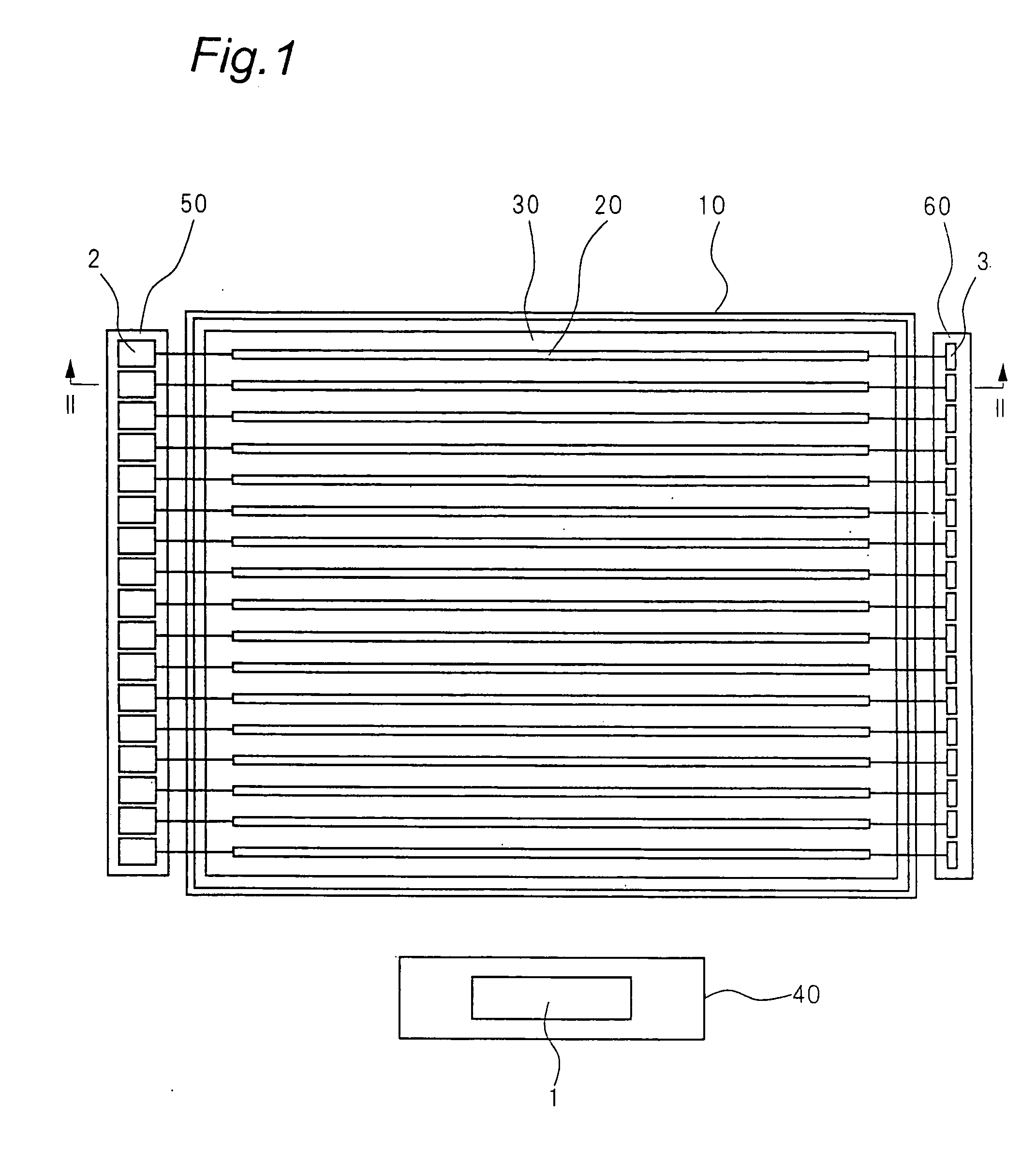
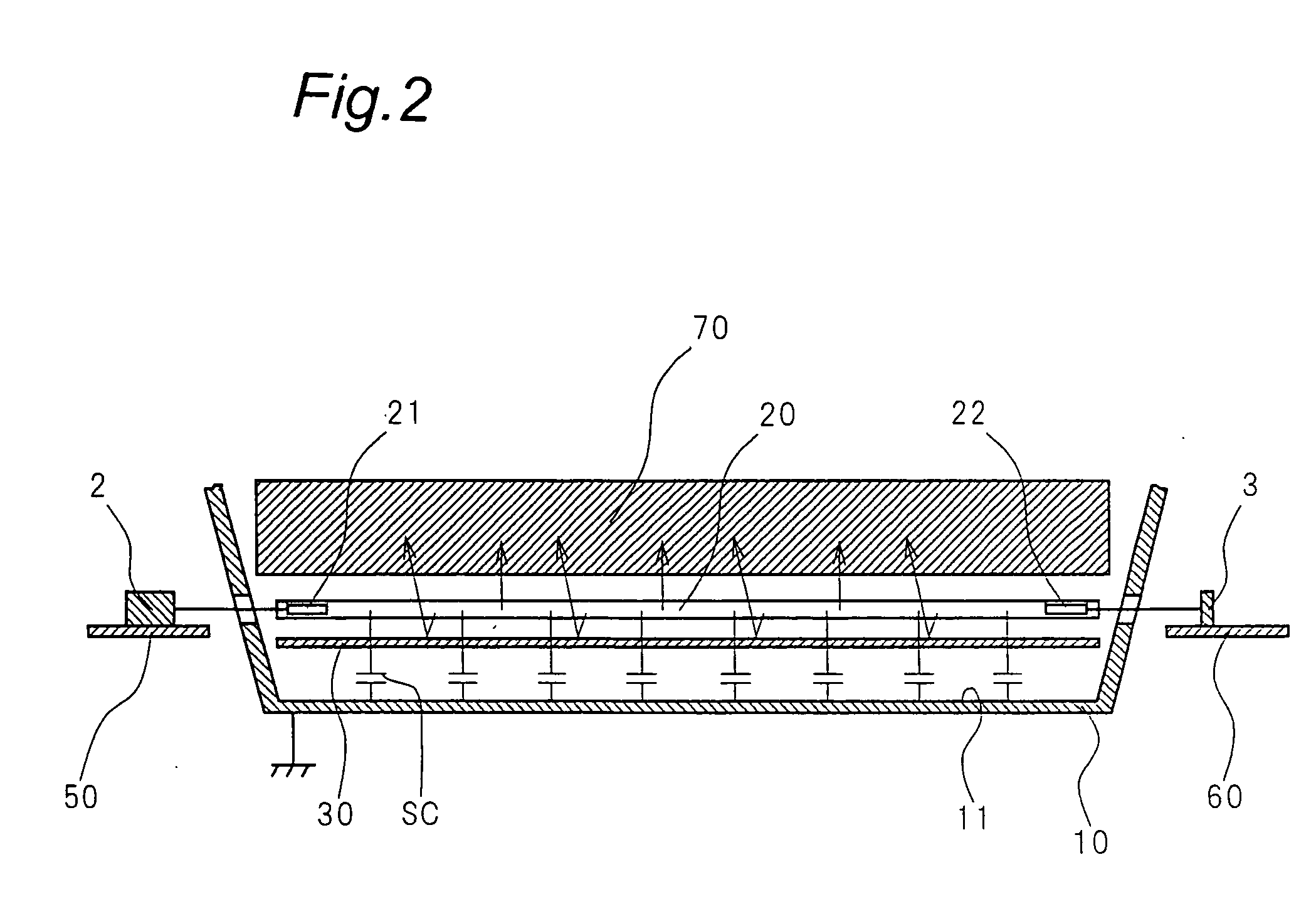
[0105]FIG. 1 is a front view showing an internal part of a liquid crystal display provided with a cold-cathode tube lighting device according to a first preferred embodiment of the present invention. FIG. 2 is a sectional view of the liquid crystal display, taken along line II-II shown in FIG. 1 (the arrows shown in FIG. 1 show a visual line direction).

[0106] The liquid crystal display includes a case 10, a plurality of cold-cathode tubes 20, a reflecting plate 30, a first substrate 40, a second substrate 50, a third substrate 60, and a liquid crystal panel 70. The cold-cathode tube lighting device according to the first preferred embodiment of the present invention is mainly divided into two blocks 1 and 2, and the blocks 1 and 2 are mounted on the first substrate 40 and the second substrate 50, respectively.

[0107] The case 10 is, for example, a box made of metal, and the box 10 is grounded. The front side of the case 10 is open, and the reflecting plate 30, the cold-cathode tube...

second preferred embodiment

[0183] A cold-cathode tube lighting device according to a second preferred embodiment of the present invention is installed in a liquid crystal display, in a manner similar to that of the device according to the first preferred embodiment described above. Since a configuration of the liquid crystal display is similar to that according to the first preferred embodiment described above, FIGS. 1 and 2, and the descriptions in the first preferred embodiment described above are incorporated to describe the configuration.

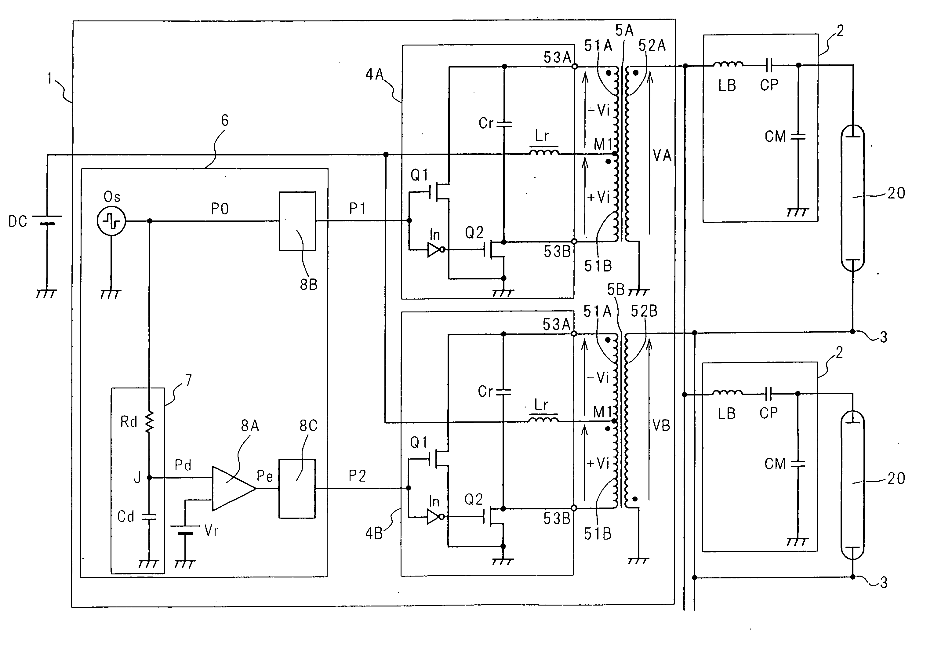
[0184]FIG. 10 is a circuit diagram showing the configuration of the cold-cathode tube lighting device according to the second preferred embodiment of the present invention. The cold-cathode tube lighting device has components similar to the components (See FIG. 3) of the device according to the first preferred embodiment, except for the configuration of the second block 2. Accordingly, the similar components are designated by the same numerals shown in FIG. 3, and the de...

third preferred embodiment

[0208] A cold-cathode tube lighting device according to a third preferred embodiment of the present invention is installed in a liquid crystal display, in a manner similar to that of the device according to the first preferred embodiment described above. Since a configuration of the liquid crystal display is similar to that according to the first preferred embodiment described above, FIGS. 1 and 2, and the descriptions in the first preferred embodiment described above are incorporated to describe the configuration.

[0209]FIG. 11 is a circuit diagram showing the configuration of the cold-cathode tube lighting device according to the third preferred embodiment of the present invention. The cold-cathode tube lighting device has components similar to the components (See FIG. 3) of the device according to the first preferred embodiment, except for the configuration of the first block 1. Accordingly, the similar components are designated by the same numerals shown in FIG. 3, and the descri...


PUM

PropertyMeasurementUnit
frequencyaaaaaaaaaa
frequencyaaaaaaaaaa
inductanceaaaaaaaaaa

Abstract

A cold-cathode tube lighting device uniformly lights a plurality of cold-cathode tubes using a common power source, and maintains the luminance of each cold-cathode tube uniformly in the longitudinal direction thereof at high precision. A first block converts a direct-current voltage to one pair of alternating-voltages. Since leakage impedances of step-up transformers are low, the first block functions as one pair of low-impedance power sources. Each second block is connected to each cold-cathode tube. A ballast inductor stabilizes tube current by resonating with a matching capacitor during lighting of the cold-cathode tube. A combined impedance of the matching capacitor and a peripheral stray capacitance is matched with an impedance of the ballast inductor, for each cold-cathode tube. Since a delay circuit shifts phases of two pulse waves with respect to each other, a phase difference between the alternating-voltages is shifted from 180°.

Description

TECHNICAL FIELD [0001] The present invention relates to a cold-cathode tube lighting device. In particular, the present invention relates to a device for lighting a plurality of cold-cathode tubes. BACKGROUND ART [0002] Fluorescent tubes are classified roughly into hot-cathode tubes and cold-cathode tubes depending on the configuration of the electrodes thereof. The electrodes of a cold-cathode tube (also referred to as a CCFL) are formed of substances that emit numerous electrons through the application of high voltage. Namely, the electrodes do not include any filaments for emitting thermal electrons, unlike the case of the hot-cathode tubes. For this reason, the cold-cathode tubes are particularly advantageous over the hot-cathode tubes in terms of very small tube diameter, long life and low power consumption. Because of the advantages, the cold-cathode tubes are mainly used frequently for products strongly requested to be made thinner (or smaller in size) and lower in power cons...

Claims


Application Information

Patent Timeline
Patent Type & Authority Applications(United States)
IPC IPC(8): H05B39/00H05B41/24H01F27/32H01F38/10H02M7/48H05B41/282
CPCG02F1/133604H01F27/326H01F38/10H05B41/2822
Inventor KOMATSU, AKEYUKIMIYAKE, EIJIKAWATAKA, KENJI
Owner PANASONIC CORP
Why Eureka
Try Eureka