
Methods and apparatus for advanced wind turbine design

a technology of advanced wind turbines and wind turbines, applied in the direction of electric generator control, fluid couplings, greenhouse gas reduction, etc., can solve the problems of loss of energy, cost, complexity, and complexity of conversion stages to achieve the effect of slowing down the pressure level of high pressure tanks

Active Publication Date: 2007-06-21
MCCLINTIC FRANK
View PDF15 Cites 34 Cited by
  • Summary
  • Abstract
  • Description
  • Claims
  • Application Information

AI Technical Summary

Benefits of technology

This solution enables direct grid-frequency compatibility without additional conversion stages, provides more uniform power output, expands energy absorption bandwidth, and allows self-starting capabilities, reducing grid load and improving energy efficiency and storage capacity.

Problems solved by technology

In such designs, there is an inherent problem in that as the wind speed varies the output frequency of the generator will also vary.
Such conversion stages can be costly and complex to implement and maintain.
In addition, there is an inherent inefficiency which results in the frequency conversion process resulting in lost energy.
Current wind turbines designs which connect to a power grid provide no or very limited warning of the loss of output due to unfavorable wind conditions.
Loss of generator output can be due to low wind or no wind conditions resulting in insufficient wind energy to continue to drive the turbine.
Loss of generator output can also be due to high wind conditions which could overstress the wind turbine elements if the wind turbine operation was allowed to continue, and thus the wind turbine is typically intentionally taken off-line during the interval of detected high winds to prevent damage to the wind turbine.
Inconsistencies of the wind turbine generator output power level and rapid cutoffs result in balancing problems from the perspective of power grid management.
In many cases, a low velocity wind does not provide enough energy to start the rotation of the wind turbine so power from the grid is needed to drive a motor to start the spinning.
Wind turbine start-up energy requirements place additional loads on the power grid.
In a grid coupled to a larger number of similar or identical wind turbines in the same general area subject to the approximately the same wind conditions, it would not be unusual for many of these wind generator turbines to try to start up at approximately the same time, thus placing a substantial short term additional load on the grid.
Another problem facing current wind turbines is that the energy absorption bandwidth is typically rather narrow.
However, implementing a large turbine blade area designed to accommodate the capture of wind energy at relatively low wind velocities becomes a detriment to the capture of wind energy at relatively high wind velocities, as the larger size blades increase the likelihood of potential structural failure at the high wind velocities.
Current wind turbines have very limited or no energy storage capability.

Method used


Image

  • Methods and apparatus for advanced wind turbine design
  • Methods and apparatus for advanced wind turbine design
  • Methods and apparatus for advanced wind turbine design

Examples


Embodiment Construction

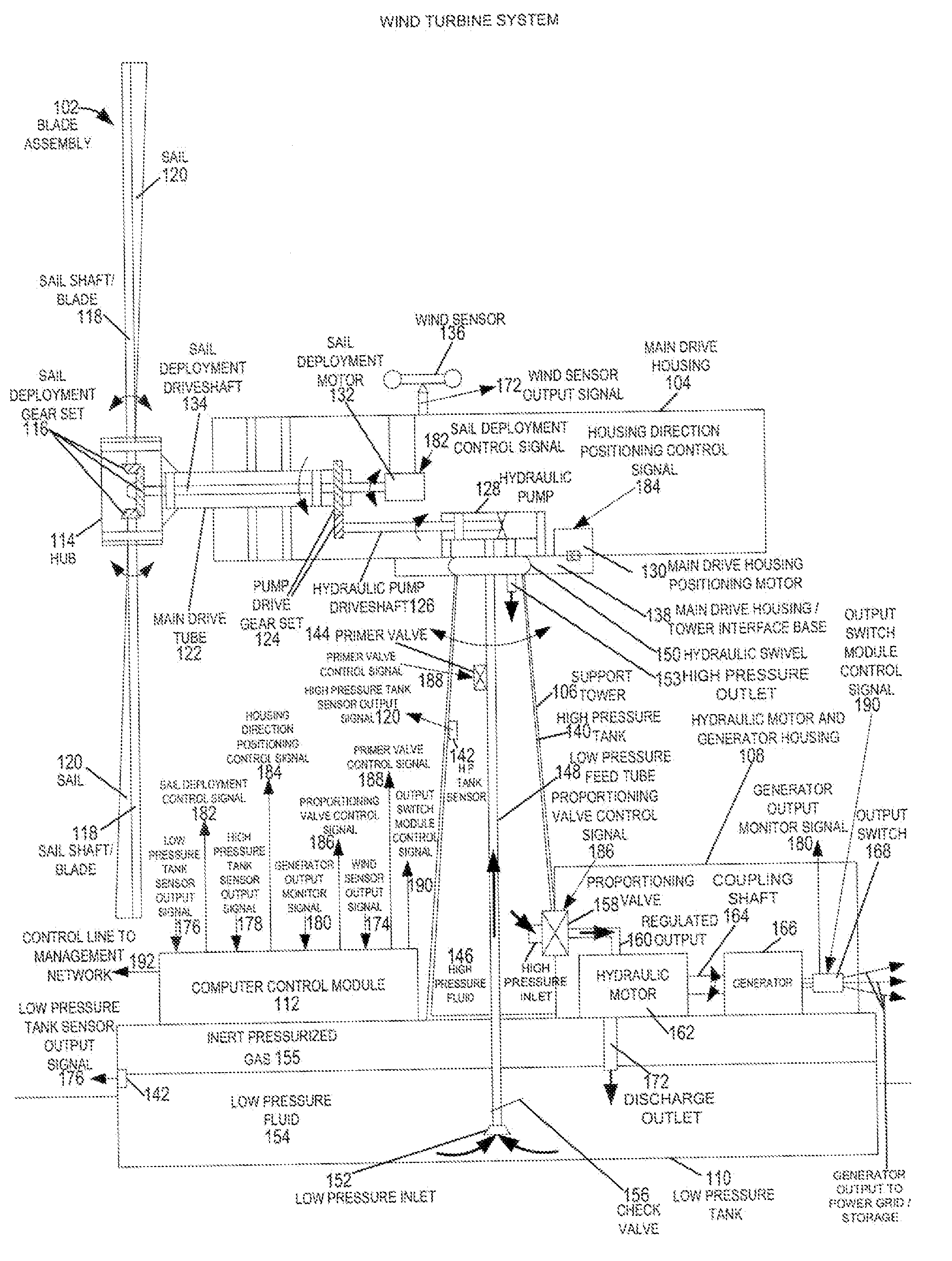
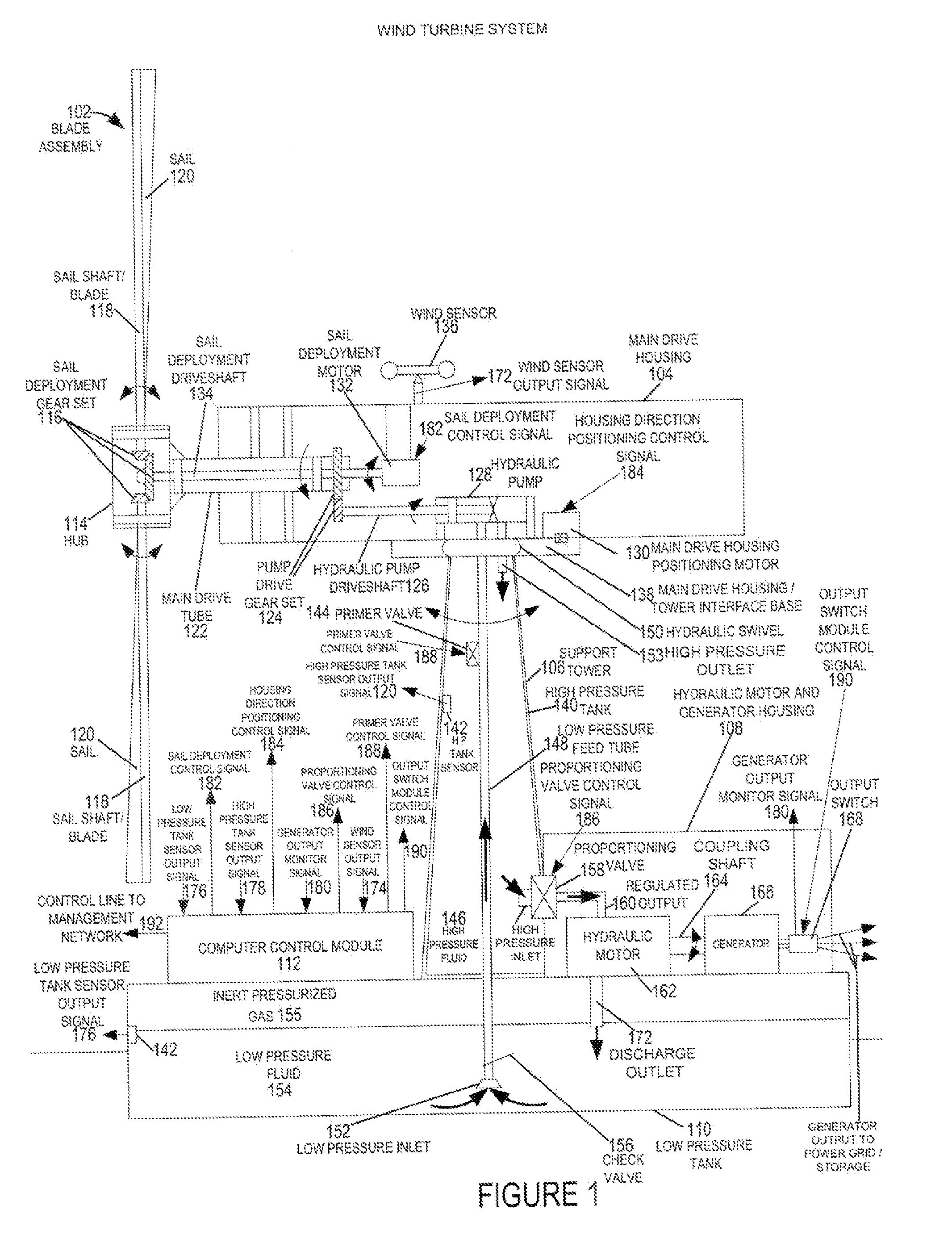
[0032]FIG. 1 is a drawing of an exemplary wind turbine system 100 implemented in accordance with the present invention and using methods of the present invention. Exemplary wind turbine system 100 includes a blade assembly 102, a main drive housing 104, a support tower 106, a hydraulic motor and generator housing 108, a low pressure tank 110, and a computer control module 112.

[0033] The blade assembly 102 includes a hub 114, a sail deployment gear set 116, a plurality of sail shafts / blades 118, and a plurality of retractable sails 120. The blade assembly 102 is used to capture wind energy. The blade assembly 102, in some embodiments includes a rolling reefing sail system, whereby the area of the sails is variably adjustable. The sail shaft / blades 118, e.g., carbon fiber masts, coupled to hub 114 are attached to the sail deployment gear set 116, and can be rotated to let out or retract the sails 120 which are attached to the sail shaft / blades 118. In some embodiments, sensors are em...


PUM


Abstract

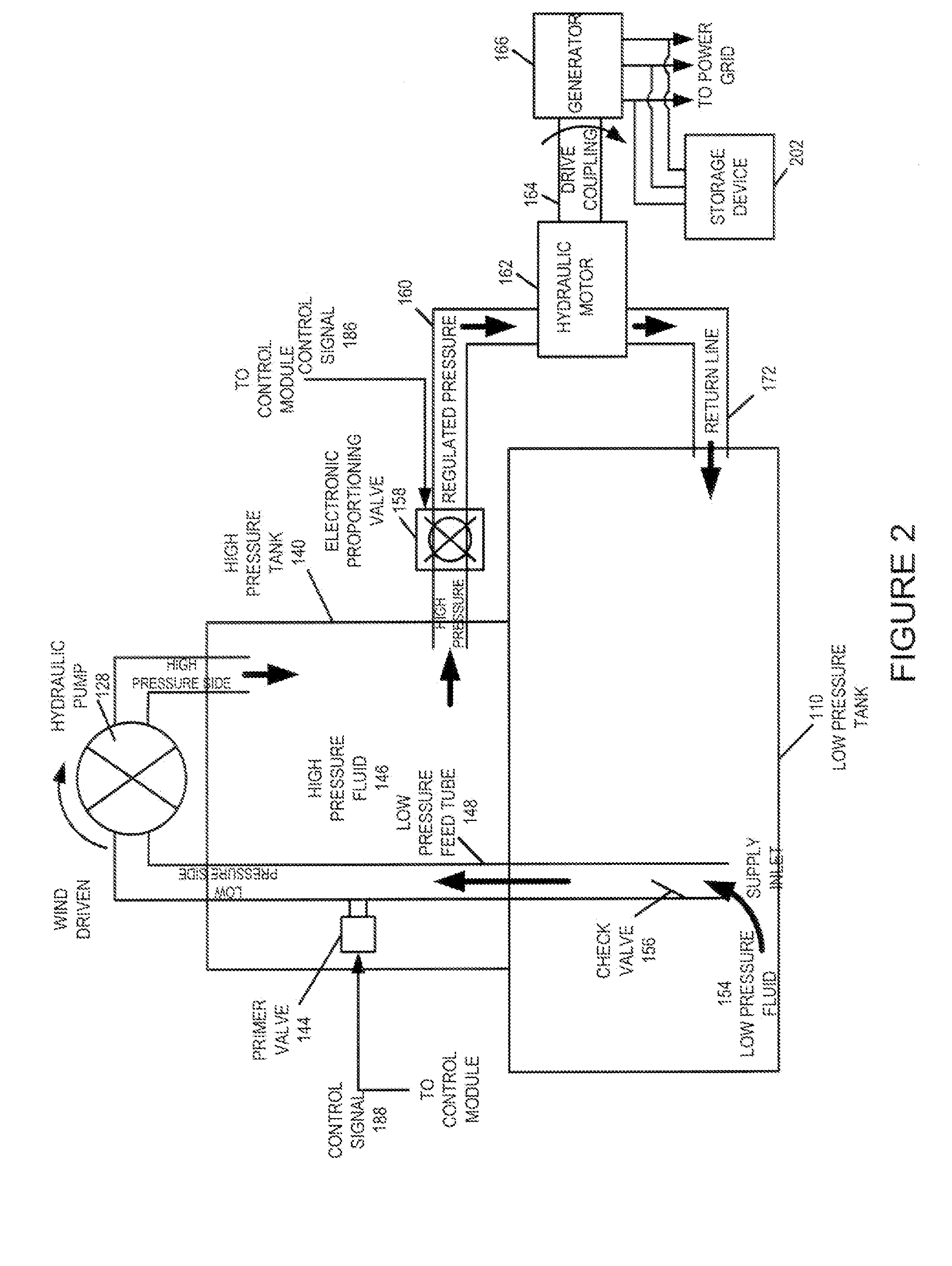
A wind turbine system includes a variable blade assembly including adjustable sails and wing shaped masts expanding the wind velocity capture envelope. The blade assembly turns a hydraulic pump, which pressurizes fluid and stores the pressurized fluid in a chamber in the support tower. Pressurized fluid is directed via an electronically controllable proportioning valve to a hydraulic motor which is coupled to an electric generator. A computer control module operates the proportioning valve regulating pressure to the hydraulic motor, maintaining generator rotational speed, and providing consistent output frequency to the power grid. Stored energy in the high pressure tank is used to continue generator operation after the winds cease, allowing early warning notification to the power management system of impending power loss. Residual pressure maintained in the high pressure tank allows restart operations via hydraulic pressure rather than power grid energy drain. On site high energy capacitors store additional energy.

Description

RELATED APPLICATIONS [0001] The present application is a continuation of U.S. patent application Ser. No. 11 / 190,687 which was filed on Jul. 27, 2005 and which is hereby expressly incorporated by reference.FIELD OF THE INVENTION [0002] The present invention relates to alternative energy sources, and more particularly, to methods and apparatus for advanced wind turbine design. BACKGROUND [0003] Current wind turbine designs typically utilize direct drive generators or gear driven generators coupled to the wind turbine shaft. In such designs, there is an inherent problem in that as the wind speed varies the output frequency of the generator will also vary. However, for the generator output to be usable by the power grid, the output signal needs to be converted to match the power grid frequency, which is 60 Hz in the United States and 50 Hz in Europe. Typically, an additional frequency conversion stage is used to convert from the variable wind turbine generator output frequency to the c...

Claims


Application Information

Patent Timeline
Patent Type & Authority Applications(United States)
IPC IPC(8): F03D9/00H02P9/04
CPCF03D7/0236F03D9/001F03D9/021F03D9/028F05B2240/3121F05B2260/406Y02E10/721Y02E60/15Y02E10/723Y02E60/17F03D9/11F03D9/17F03D9/25F03D9/28F03D13/20F03D15/10F03D17/00F03D80/80Y02E10/72Y02E10/728Y02E60/16Y02E70/30Y02P80/10Y02P90/50
Inventor MCCLINTIC, FRANK J.
Owner MCCLINTIC FRANK
Learn More