Self-expanding stent delivery system

Inactive Publication Date: 2007-06-21
CORDIS CORP
View PDF6 Cites 15 Cited by
  • Summary
  • Abstract
  • Description
  • Claims
  • Application Information

AI Technical Summary

Benefits of technology

[0010]The various aspects of the systems and methods of the invention described herein provide a delivery sy

Problems solved by technology

Delivering the stent the entire length of the catheter sheath can pose problems however, including damage to the vessel or the stent during deployment.
Preloading the stent at the distal end of the catheter, as in U.S. Pat. No. 4,732,152 issued to Wallsten, et al. on Mar. 22, 1988, can pose other problems.
Such problems include embedding of the stent in the interior surface of the distal end of the catheter or other conduit within the distal end of the cathet

Method used


Image

  • Self-expanding stent delivery system
  • Self-expanding stent delivery system
  • Self-expanding stent delivery system

Examples


Embodiment Construction

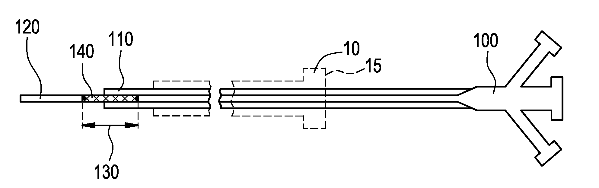
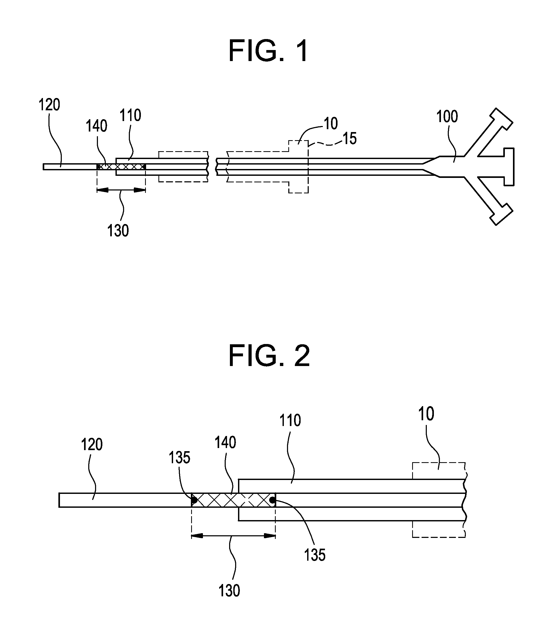
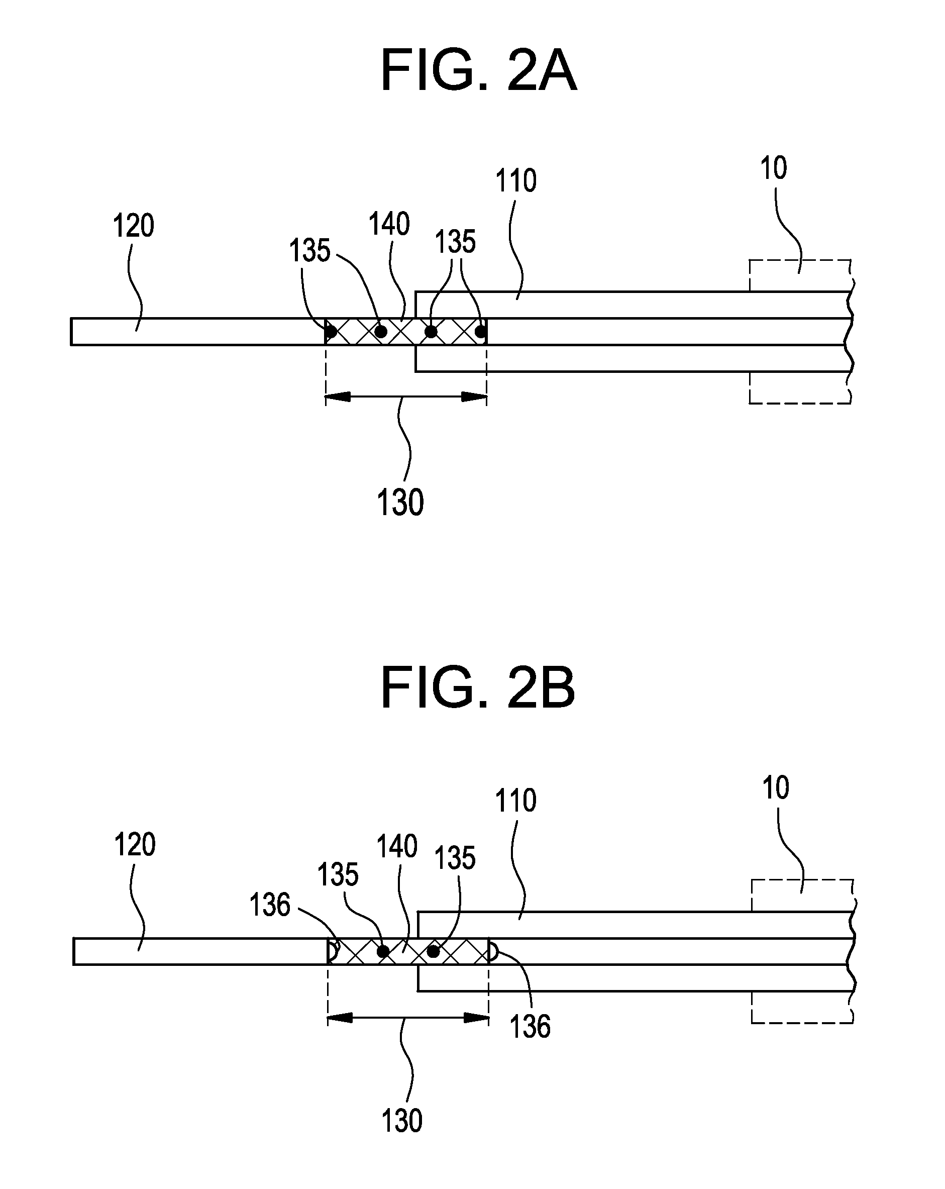
[0024]FIG. 1 illustrates a system for delivering a self-expanding stent to an intended treatment site in the vasculature of a patient, for example. The system generally comprises an introducer 10 (shown in dashed lines) and a delivery catheter 100. The delivery catheter 100 is insertable into the introducer 10 and secured by a valve 15, for example, in conventional manner, so as to restrict the delivery catheter 100 from undesirable movement when insertion and navigation of the delivery catheter 100 through the vasculature occurs. The valve 15 also minimizes, or ideally precludes, leakage of bodily fluids through the introducer where possible. The various components of the delivery system described herein are sized according to physiological and medical needs to accommodate a range of vessels or other anatomical passageways, as should be appreciated by the artisan.

[0025]Referring still to FIG. 1, the delivery catheter 100 further comprises an outer body 110, an inner body 120, and a...


PUM


Abstract

Self-expanding stent delivery systems and methods having an introducer that receives a delivery catheter. The delivery catheter includes an outer body, an inner body and a stent loaded onto a stent bed within the inner body. The outer body receives the inner body with the stent loaded on the stent bed thereof. The outer body helps constrain the stent in its undeployed state in the stent bed until the stent is deployed by retraction of the outer body of the delivery catheter when the stent is identified as positioned across an intended treatment site. At least one anchoring mechanism provided on the inner body helps maintain the undeployed loaded stent appropriately in the stent bed during deployment. The at least one anchoring mechanism can include radiopaque material to increase fluoroscopic visualization of the stent during deployment, and the self-expanding stent can be a bio-absorbable material including drugs or other bio-active agents incorporated therein or provided thereon. The at least one anchoring mechanism can instead comprise a set of at least two bumpers between which the stent is loaded until deployed by retraction of the outer body of the delivery catheter when the stent has been appropriately positioned across an intended treatment site. After deployment of the stent at the intended treatment site, removal of the inner body and outer body of the delivery catheter and of the introducer occurs. Reliable and accurate emplacement of the stent across an intended treatment site is rendered more likely as a result.

Description

BACKGROUND OF THE INVENTION[0001]1. Field of the Invention[0002]The invention generally relates to a delivery system for emplacing a self-expanding stent within a vessel or other passageway of a patient.[0003]2. Related Art[0004]Stents for maintaining or restoring the patency of an anatomical passageway of a patient are commonly used to minimize the invasiveness otherwise associated with a surgical exposure of a treatment site. In the case of endovascular implantation of a stent into a blood vessel, percutaneous deployment is initiated by an incision into the vascular system of the patient, typically via the femoral or carotid artery. A tubular or sheath portion of an introducer is inserted through the incision and into the artery. A central lumen through the introducer provides a passageway through the patient's skin and artery wall into the interior of the artery. An outwardly tapered hub portion of the introducer remains outside the patient's body to prevent blood from leaking ou...

Claims


Application Information

Patent Timeline
IPC IPC(8): A61F2/06
CPCA61F2/95A61F2002/9665
Inventor DAVE, VIPUL BHUPENDRASANCHEZ, DIANA MARGARITA
Owner CORDIS CORP
Why Eureka
Try Eureka