Method and system for development of hydrocarbon bearing formations including depressurization of gas hydrates

a gas hydrate and hydrocarbon bearing technology, applied in the field of gas recovery system and method for subterranean gas hydrate formation, can solve the problems of not having enough methane and water production, etc., to achieve the effect of shortening the life of the pump and affecting the formation stability

Active Publication Date: 2007-06-28
SCHLUMBERGER TECH CORP
View PDF11 Cites 47 Cited by
  • Summary
  • Abstract
  • Description
  • Claims
  • Application Information

AI Technical Summary

Benefits of technology

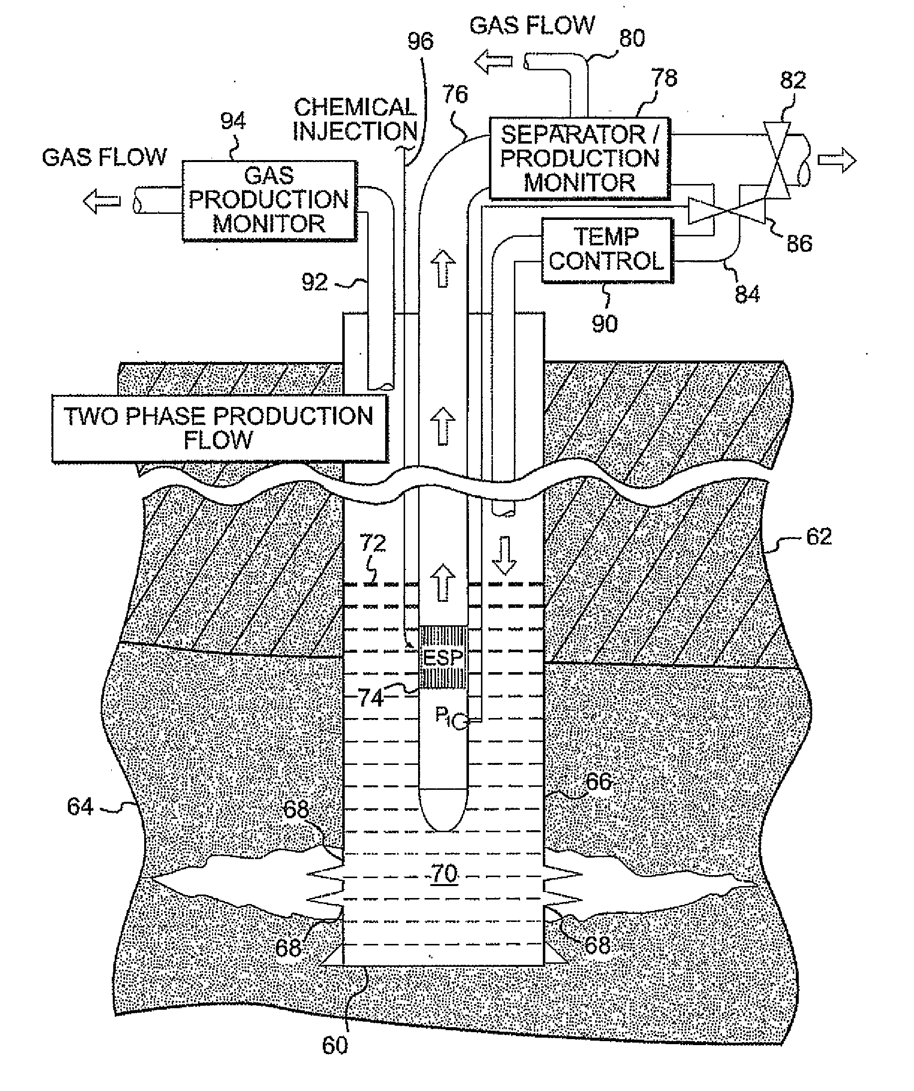
[0013] One way production rate can be controlled is by switching a downhole submersible pump ON and OFF, or by changing the operating frequency of the pump. However, switching the pump ON and OFF can drastically shorten the life of a pump. Also the water hammer effect of the on / off operation can affect the formation stability. On the other hand, each pump has a fixed range of pump rates to operate on. But with fluctuations in the expected production rates of hydrocarbon bearing wells, e.g., gas hydrates, no known existing pumps can handle the wide range of pump rates.

Problems solved by technology

Some gas hydrate reservoirs, however, do not have enough production or enough stable production flows of methane and water to maintain a minimum flow rate especially in the beginning of production operations when the hydrate layer may have very low permeability yielding low levels of production.
However, switching the pump ON and OFF can drastically shorten the life of a pump.
Also the water hammer effect of the on / off operation can affect the formation stability.
But with fluctuations in the expected production rates of hydrocarbon bearing wells, e.g., gas hydrates, no known existing pumps can handle the wide range of pump rates.
But in this case, a pump change would be needed when production rate exceeds pump capacity.

Method used


Image

  • Method and system for development of hydrocarbon bearing formations including depressurization of gas hydrates
  • Method and system for development of hydrocarbon bearing formations including depressurization of gas hydrates
  • Method and system for development of hydrocarbon bearing formations including depressurization of gas hydrates

Examples


Embodiment Construction

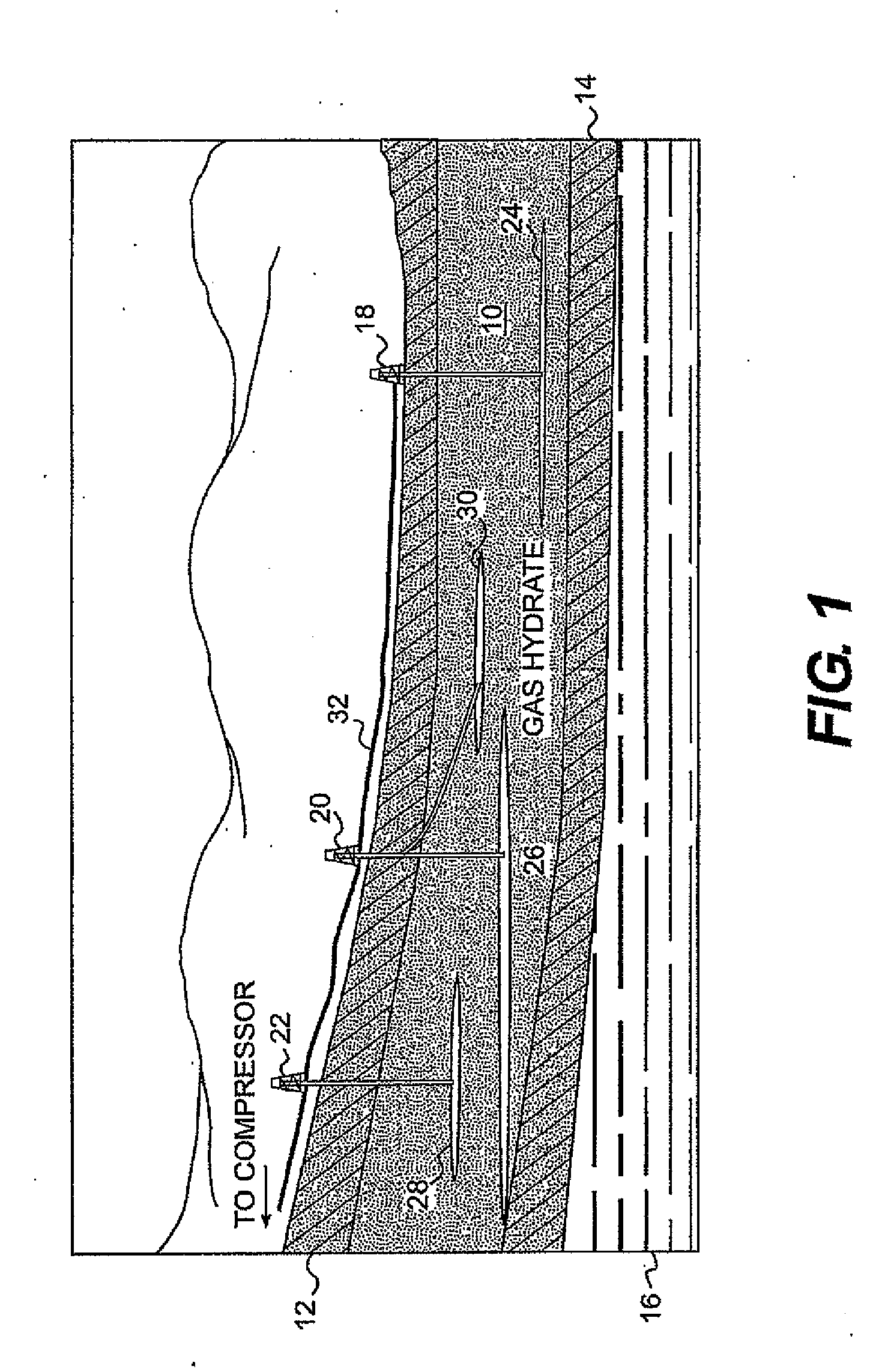
[0024] Turning now to the drawings wherein like numerals indicate like parts, FIG. 1 discloses a pictorial representation of one operating context of the invention. In this view a band of gas hydrate 10 lies in a rather shallow geologic zone beneath a permafrost layer 12 such as exists in Alaska. Other earth formations 14 and / or aquifer regions 16 can exist beneath the gas hydrate.

[0025] In order to recover sequestered methane gas from within the gas hydrate zone one or more wells 18, 20 and / or 22 are drilled through the permafrost 12 and into the gas hydrate zone 10. Usually a casing is cemented within the well and one or more windows are opened directly into the hydrate zone to depressurize irregular regions of the gas hydrate represented by irregular production zones 24, 26, 28 and 30 extending away from distal terminals of the wells. Although a single well is shown drilled from a single derrick illustrated at 18 and 22 it is envisioned that directional drilling as illustrated a...


PUM


Abstract

A method and system for the production of a gas hydrate including the steps of drilling into a subterranean gas hydrate formation and at least partially depressurizing the gas hydrate formation to permit separation of gas and water from the hydrate form. The gas and water is then pumped from the formation and recovered from the well. At least a portion of water pumped from the well is water that is introduced into the well from the surface or reintroduced by a feed back loop from the production operation.

Description

CROSS-REFERENCE TO RELATED APPLICATION [0001] This application relates to and claims the benefit under 35 U.S.C. § 119(e) of applicants' U.S. Provisional Application Ser. No. 60 / 752,118 entitled “Systems and Method for Development of Hydrocarbon Bearing Formations,” filed Dec. 20, 2005. The disclosure of this Provisional Application is hereby incorporated by reference as though set forth at length.BACKGROUND [0002] This invention is generally related to a method and system for recovering gas from subterranean gas hydrate formations. More particularly, this invention relates to a method and system for producing methane gas sequestered within subterranean methane hydrates. [0003] A gas hydrate is a crystalline solid that is a cage-like lattice of a mechanical intermingling of gas molecules in combination with molecules of water. The name for the parent class of compounds is “clathrates” which comes from the Latin word meaning “to enclose with bars.” The structure is similar to ice but...

Claims


Application Information

Patent Timeline
Patent Type & Authority Applications(United States)
IPC IPC(8): E21B47/06E21B43/00
CPCE21B23/02E21B43/08E21B43/119E21B2043/0115E21B41/0099
Inventor SUGIYAMA, HITOSHICHO, BRIAN W.ONODERA, SHUNETSUAL-JUBORI, AHMED H.FUKUHARA, MASAFUMI
Owner SCHLUMBERGER TECH CORP
Why Eureka
Try Eureka