Polycrystalline ultra-hard material with microstructure substantially free of catalyst material eruptions

Active Publication Date: 2007-06-28
SMITH INT INC
9 Cites 77 Cited by

AI-Extracted Technical Summary

Problems solved by technology

A problem known to exist with such conventional PCD materials is that during such single-step HPHT process, one or more constituent materials in the substrate are known to melt and infiltrate into the diamond grain volume so rapidly that that results in the eruption of such one or more constituent materials from the substrate and into the adjacent diamond grain volume.
The presence of such columns or localized concentrations of the catalyst material is not desired because: (1) they can reduce the effective amount of the diamond grains that are bonded together during HPHT processing due to the concentrated rather than distributed arrangement of the of the catalyst material within the diamond grain v...

Benefits of technology

[0015] In such example embodiment, the first HPHT process condition is held at a temperature that is sufficient to melt the catalyst material and cause a partial amount of catalyst material infiltration into the precursor polycrystalline ultra-hard material. During this first HPHT process condition, it is desired tha...

Abstract

Polycrystalline ultra-hard materials and compacts comprise an ultra-hard material body having a polycrystalline matrix of bonded together ultra-hard particles, e.g., diamond crystals, and a catalyst material disposed in interstitial regions within the polycrystalline matrix. The material microstructure is substantially free of localized concentrations, regions or volumes of the catalyst material or other substrate constituent. The body can include a region extending a depth from a body working surface and that is substantially free of the catalyst material. The compact is produced using a multi-stage HPHT process, e.g., comprising two HPHT process conditions, wherein during a first stage HPHT process the catalyst material is melted and only partially infiltrates the precursor ultra-hard material, and during a second stage further catalyst material infiltrates the precursor ultra-hard material to produce a fully sintered compact.

Application Domain

Drill bitsConstructions +4

Technology Topic

MicrostructureSuperhard material +2

Image

  • Polycrystalline ultra-hard material with microstructure substantially free of catalyst material eruptions
  • Polycrystalline ultra-hard material with microstructure substantially free of catalyst material eruptions
  • Polycrystalline ultra-hard material with microstructure substantially free of catalyst material eruptions

Examples

  • Experimental program(1)

Example

EXAMPLE
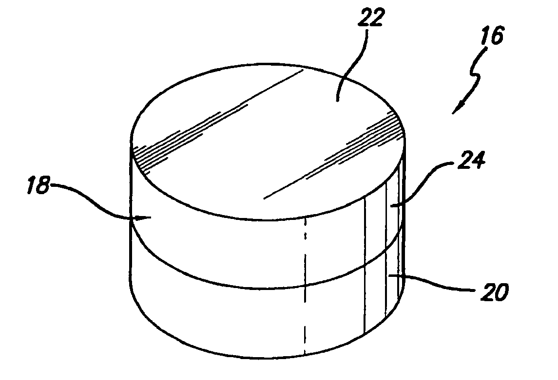
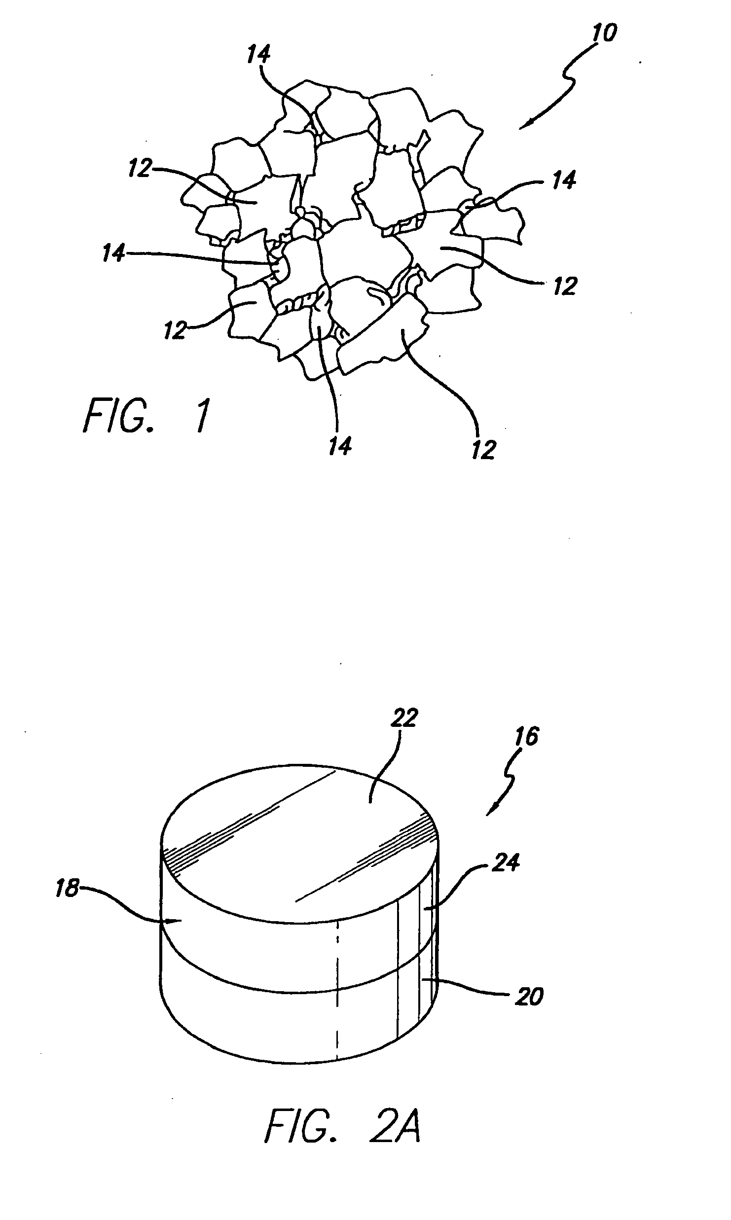
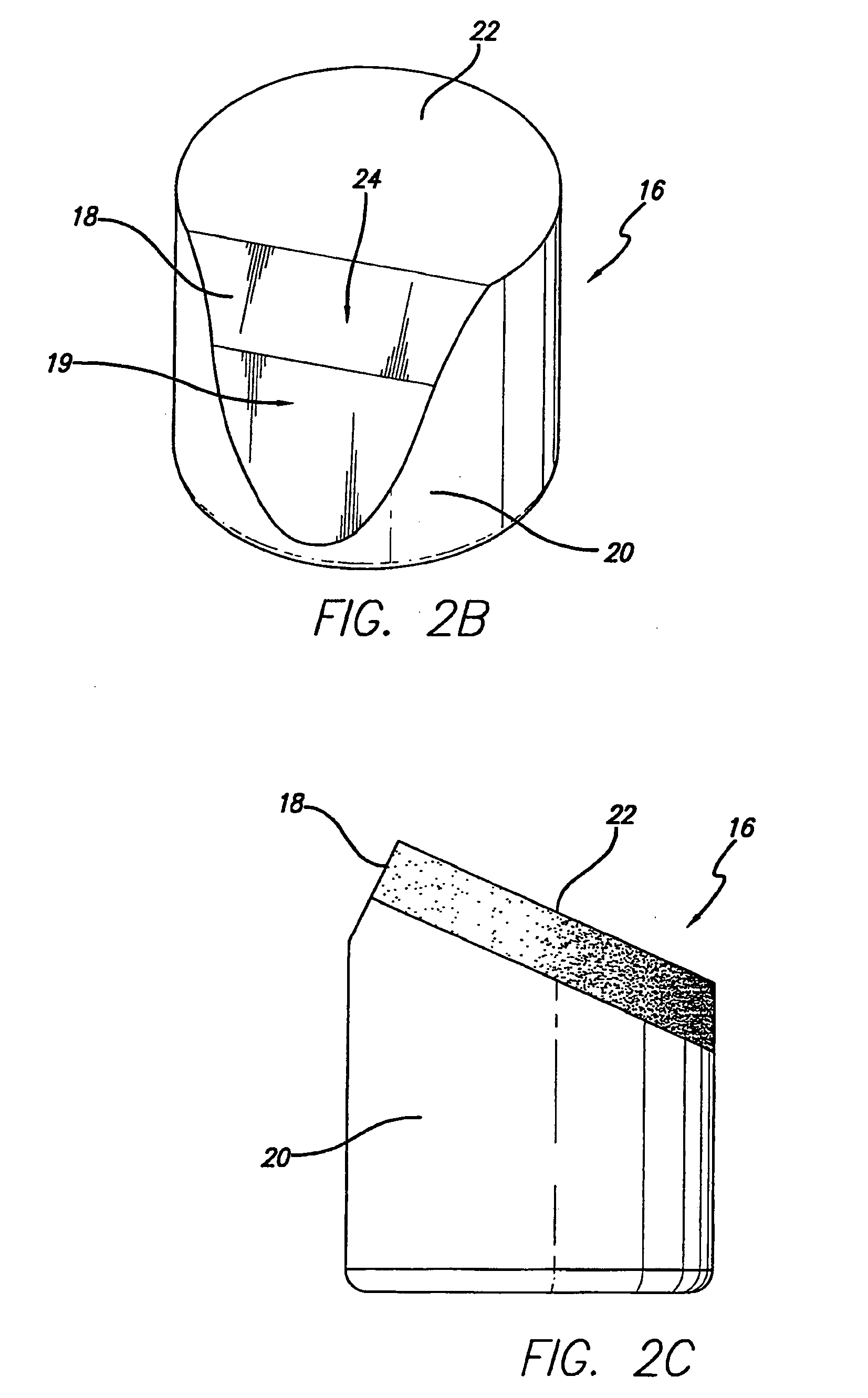
Polycrystalline Ultra-Hard Material Compact
[0072] Synthetic diamond powder having an average grain size of approximately 2 to 50 micrometers was mixed together for a period of approximately 2 to 6 hours by ball milling. The resulting mixture was cleaned by processing in a hydrogen reduction furnace cycle. The mixture was loaded into a refractory metal container. A WC—Co substrate was positioned adjacent a surface of the diamond powder volume. The container was surrounded by pressed salt (NaCl) and this arrangement was placed within a graphite heating element. This graphite heating element containing the pressed salt and the diamond powder and substrate encapsulated in the refractory container was then loaded in a vessel made of a high pressure/high temperature self-sealing powdered ceramic material formed by cold pressing into a suitable shape.
[0073] The self-sealing powdered ceramic vessel was placed in a hydraulic press having one or more rams that press anvils into a central cavity. The press was operated to impose a first stage HPHT process condition of approximately 5,500 MPa and approximately 1,350° .C on the vessel for a period of approximately 150 seconds. During this first stage HPHT process condition, cobalt from the WC—Co substrate was melted and started to infiltrate into an adjacent region of the diamond powder mixture. During this first stage HPHT process condition, greater than about 10 percent by volume of the cobalt infiltrated into the adjacent diamond powder mixture.
[0074] The press was then operated to impose a second stage HPHT process condition of approximately 5,500 MPa and approximately 1500° C on the vessel for a period of approximately 300 seconds. During this second stage HPHT process condition, further melted cobalt from the WC—Co substrate infiltrated into the diamond powder mixture, intercrystalline bonding between the diamond crystals and bonding took place forming a fully sintered PCD body, and bonding between the PCD body and the substrate took place forming a PCD compact.
[0075] The vessel was opened and the resulting PCD compact was removed therefrom. The microstructure of the PCD body was examined and found to have a microstructure comprising a polycrystalline diamond matrix substantially free of any substrate material, e.g., cobalt, eruptions. Rather, the cobalt catalyst material was observed to be dispersed evenly or in a uniform manner throughout the microstructure. There were no signs of substrate material eruptions into the PCD body, and no signs of unwanted localized concentrations, regions or volumes of any substrate constituent material, e.g., cobalt, extending through the polycrystalline diamond matrix.
[0076] A key feature of polycrystalline ultra-hard materials and compacts comprising the same, formed in accordance with the principles of this invention, is that they comprise an ultra-hard material body having a material microstructure that is substantially free of substrate material eruptions. The controlled processing of such materials and compacts using the above-described multi-stage HPHT process avoids unwanted catalyst material or other substrate constituent material eruption during formation, thereby avoiding the formation of a sintered product having an unwanted presence of localized concentrations, regions or volumes of catalyst material or other substrate constituent within the sintered microstructure.
[0077] Such localized catalyst material or other substrate constituent material concentrations caused by such eruptions are known to appear in the form of columns that extend outwardly away from the substrate and through the adjacent polycrystalline ultra-hard material body. The catalyst material columns can: (1) interfere with the effective catalytic formation of the polycrystalline ultra-hard matrix; (2) have an adverse impact on the mechanical physical properties of fracture toughness and strength of the resulting sintered product as it operates to interrupt the structure of the polycrystalline matrix; and (3) effectively reduce the thermal stability of the sintered product due to the relative thermal expansion differences between the concentrated catalyst material volumes and the polycrystalline matrix material surrounding such localized catalyst material concentrations.
[0078] Polycrystalline ultra-hard materials and compacts of this invention can be used in a number of different applications, such as tools for mining, cutting, machining and construction applications, where the combined properties of thermal stability, strength/toughness, and wear and abrasion resistance are highly desired. Polycrystalline ultra-hard materials and compacts of this invention are particularly well suited for use as working, wear and/or cutting components in machine tools and drill and mining bits, such as roller cone rock bits, percussion or hammer bits, diamond bits, and shear cutters used for drilling subterranean formations.
[0079]FIG. 7 illustrates an embodiment of a polycrystalline ultra-hard material compact of this invention provided in the form of an insert 70 used in a wear or cutting application in a roller cone drill bit or percussion or hammer drill bit. For example, such inserts 70 can be formed from blanks comprising a substrate 72 formed from one or more of the substrate materials disclosed above, and a diamond-bonded body 74 having a working surface 76. The blanks are pressed or machined to the desired shape of a roller cone rock bit insert.
[0080]FIG. 8 illustrates a rotary or roller cone drill bit in the form of a rock bit 78 comprising a number of the wear or cutting inserts 70 disclosed above and illustrated in FIG. 7. The rock bit 78 comprises a body 80 having three legs 82, and a roller cutter cone 84 mounted on a lower end of each leg. The inserts 70 can be fabricated according to the method described above. The inserts 70 are provided in the surfaces of each cutter cone 84 for bearing on a rock formation being drilled.
[0081]FIG. 9 illustrates the inserts 70 described above as used with a percussion or hammer bit 86. The hammer bit comprises a hollow steel body 88 having a threaded pin 90 on an end of the body for assembling the bit onto a drill string (not shown) for drilling oil wells and the like. A plurality of the inserts 70 is provided in the surface of a head 92 of the body 88 for bearing on the subterranean formation being drilled.
[0082]FIG. 10 illustrates a polycrystalline ultra-hard material compact of this invention as embodied in the form of a shear cutter 94 used, for example, with a drag bit for drilling subterranean formations. The shear cutter 94 comprises a diamond-bonded body 96 that is sintered or otherwise attached to a cutter substrate 98. The diamond-bonded body 96 includes a working or cutting surface 100. Shear cutters comprising the polycrystalline ultra-hard material compact of this invention can also be configured differently from that illustrated in FIG. 10, e.g., they can be configured as illustrated in FIGS. 2B to 2E.
[0083]FIG. 11 illustrates a drag bit 102 comprising a plurality of the shear cutters 94 described above and illustrated in FIG. 10. The shear cutters are each attached to blades 104 that extend from a head 106 of the drag bit for cutting against the subterranean formation being drilled.
[0084] Other modifications and variations of polycrystalline ultra-hard materials and compacts formed therefrom will be apparent to those skilled in the art. It is, therefore, to be understood that within the scope of the appended claims, this invention may be practiced otherwise than as specifically described.

PUM

PropertyMeasurementUnit
Length1.5E-5m
Fraction0.1 ~ 0.8fraction
Fraction0.25 ~ 0.6fraction

Description & Claims & Application Information

We can also present the details of the Description, Claims and Application information to help users get a comprehensive understanding of the technical details of the patent, such as background art, summary of invention, brief description of drawings, description of embodiments, and other original content. On the other hand, users can also determine the specific scope of protection of the technology through the list of claims; as well as understand the changes in the life cycle of the technology with the presentation of the patent timeline. Login to view more.
Why Eureka
Try Eureka