Low loss magnet and magnetic circuit using the same
a low-loss magnet and magnetic circuit technology, applied in the field of high-resistance magnets, can solve the problems of difficult magnet use in magnetic circuits that need high magnetic flux density or electric rotating machines that need high torque, and achieve the effect of increasing the interface and high resistan
- Summary
- Abstract
- Description
- Claims
- Application Information
AI Technical Summary
Benefits of technology
Problems solved by technology
Method used
Image

Examples
embodiment 1
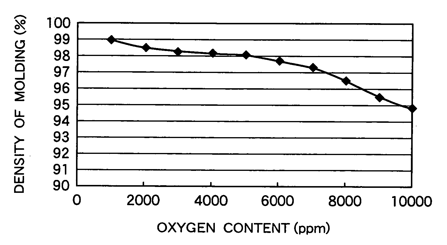
[0030] Fe alloy powder having an average particle size of 1-10 μm was prepared by grinding to which a layer containing fluorine was formed by sputtering NdF3 using a target formed of NdF3 powder in an argon gas or a nixed gas of argon and fluorine gas. Before sputtering, the surface was subjected to cleaning by reverse sputtering to remove an oxide layer on the surface thereby to lower the oxygen content to 300 ppm or less.
[0031] Vibration or rotation movement was imparted to the Fe alloy powder to form fluoride or a layer containing fluorine on the whole surface of the powder. There is on the surface of the Fe alloy powder a phase of 1 to 10 nm, which is different in a composition from that of the mother phase. The thicknesses of the phase and the oxide layer are locally different; when the powder is not homogeneous, the thicknesses are 10 to 100 nm.
[0032] The layer containing fluorine on the surface of the powder has a thickness of 1 to 10 nm or more, which is equal to that of t...
embodiment 2
[0035] Fe—Co alloy powder was prepared by grinding the alloy to an average particle size of 1 to 10 μm. CaF2 was sputtered on the surface of the Fe—Co alloy. A content of Co in the alloy is 1-30 atomic %. A target was CaF2. Sputtering was carried out in an argon gas or a mixed gas atmosphere of argon and fluorine gas to form a fluorine-containing layer on the Fe—Co alloy powder. Before sputtering of the fluoride, the surface of the powder was subjected to cleaning by reverse sputtering, etc. to remove an oxide layer so that an oxide concentration of the Fe—Co alloy powder became 3000 ppm or less.
[0036] Vibration or rotating force was imparted to the Fe—Co alloy powder to form fluoride or the fluorine-containing layer on the whole surface of the powder. There is a phase having a thickness of 1 to 10 nm, on the surface of the powder, different in the composition from that of the mother phase and normally an oxide layer around the phase.
[0037] The thickness of the fluorine containing...
embodiment 3
[0043] A treating solution for a neodymium-fluorine compound coating was prepared in the following manner. [0044] (1) 4 grams of Nd acetate or Nd nitrate, which is a salt well soluble in water, was added to about 400 mL of water, and the compound was completely dissolved by means of a shaker or ultrasonic stirrer. [0045] (2) Hydrofluoric acid of about 10% was slowly added to the solution at such an equivalent rate that NdF3 is produced by a chemical reaction. [0046] (3) The resulting solution containing gel state precipitate of NdF3 was stirred by an ultrasonic solution stirrer for more than one hour. [0047] (4) The solution was subjected to centrifugation at a rotation number of 4000 r.p.m.; then, after the supernatant was removed, almost the same amount of methanol was added. [0048] (5) After the methanol solution containing gel state NdF3 was subjected to stirring to make it a suspension solution, it was stirred by the ultrasonic stirrer for more than one hour. [0049] (6) The ste...
PUM
 Abstract
Description
Claims
Application Information
 - R&D
- Intellectual Property
- Life Sciences
- Materials
- Tech Scout
- Unparalleled Data Quality
- Higher Quality Content
- 60% Fewer Hallucinations
Browse by: Latest US Patents, China's latest patents, Technical Efficacy Thesaurus, Application Domain, Technology Topic, Popular Technical Reports.
© 2025 PatSnap. All rights reserved.Legal|Privacy policy|Modern Slavery Act Transparency Statement|Sitemap|About US| Contact US: help@patsnap.com