High velocity spray technique for medical implant components

a high-speed spraying and medical implant technology, applied in the direction of prosthesis, packaging foodstuffs, impression caps, etc., can solve the problems that the present spraying operation cannot be performed in vacuum or near vacuum conditions

Inactive Publication Date: 2007-07-05
HOWMEDICA OSTEONICS CORP
View PDF25 Cites 33 Cited by
  • Summary
  • Abstract
  • Description
  • Claims
  • Application Information

AI Technical Summary

Benefits of technology

[0008] In accordance with an aspect of the present invention, a method of providing a reactive material on at least one portion of a surface of a substrate of a medical implant component is provided. Such method may comprise the steps of arranging the medical implant component in a holding fixture in which the holding fixture is capable of holding the medical implant component at atmospheric or substantially atmospheri

Problems solved by technology

As such, present spraying operation may not be p

Method used


Image

  • High velocity spray technique for medical implant components
  • High velocity spray technique for medical implant components
  • High velocity spray technique for medical implant components

Examples


Embodiment Construction

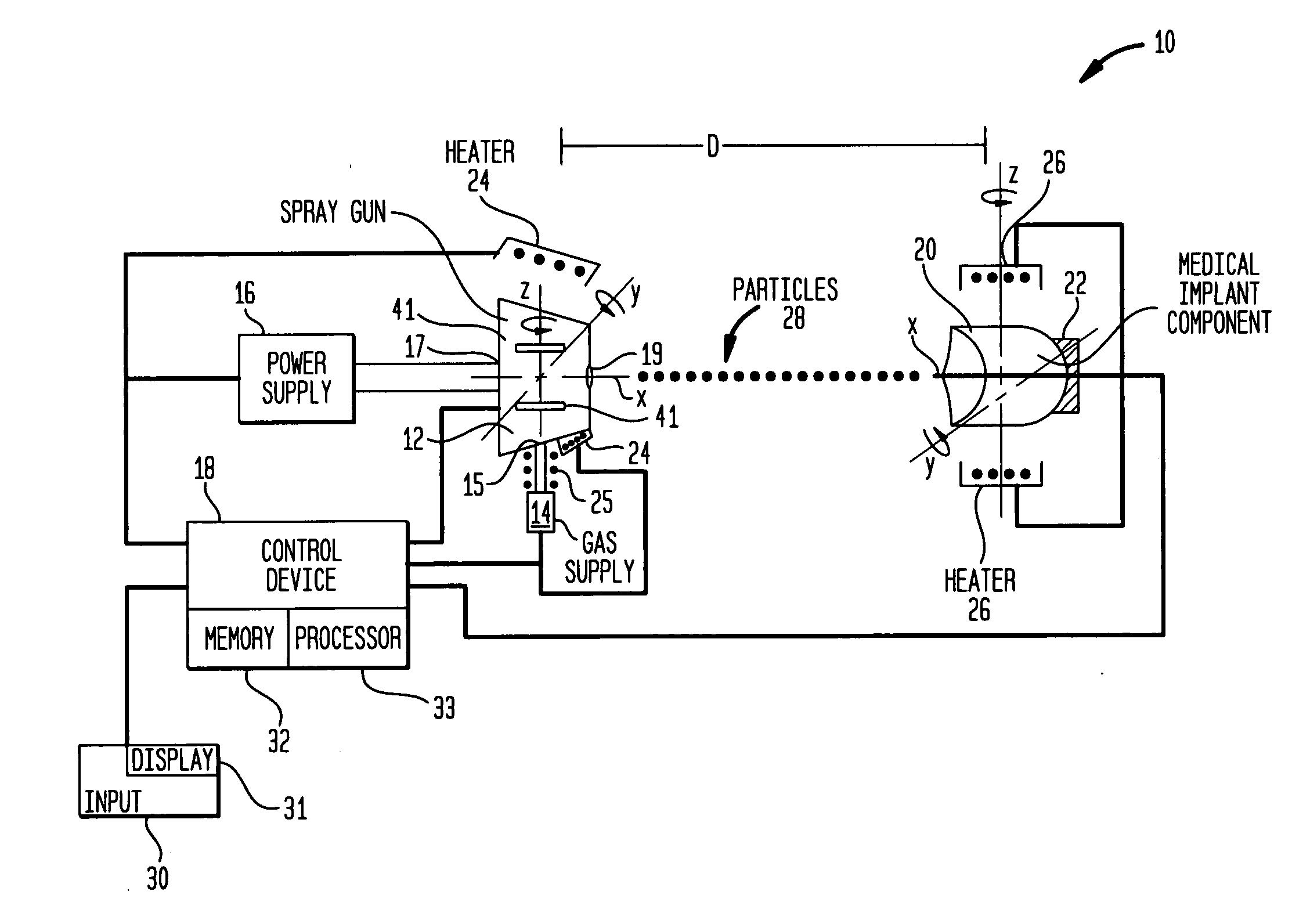
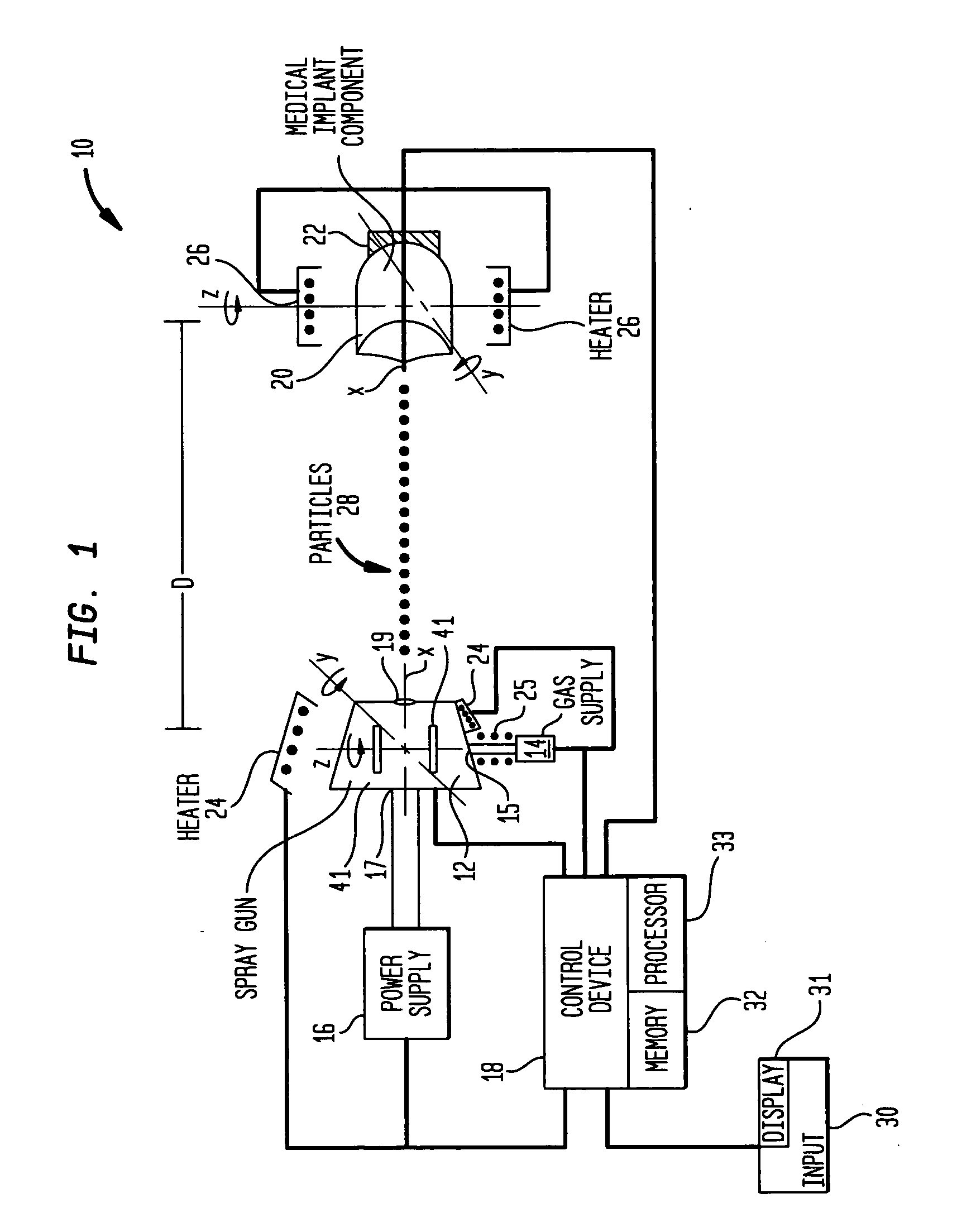
[0017] A technique for enabling a component, such as a medical implant component, to be sprayed with a desired material in accordance with an embodiment of the present invention will now be described initially with reference to system 10 illustrated in FIG. 1. As shown therein, such system may generally include a spray nozzle or gun 12, a control device 18, and a holding fixture 22.

[0018] The spray gun 12 may include two inlets, a gas inlet 15 and a powder feed inlet 17. The gas inlet 15 may be adapted to receive a gas from a gas supply 14 under relatively high pressure. Such gas may be a low density gas such as helium which may enable higher gas velocities as compared to lower density gases. The powder feed inlet 17 may be adapted to receive material to be sprayed in a powder or small particle form from a powder supply 16 under relatively high pressure. The spray gun 12 may include one or more internal chambers for receiving the gas and the spray material and for directing the spr...


PUM

PropertyMeasurementUnit
Fractionaaaaaaaaaa
Fractionaaaaaaaaaa
Thicknessaaaaaaaaaa

Abstract

Method of providing a desired material on at least a portion of a surface of a substrate of a component, such as a medical implant component. The method may comprise the steps of arranging the component in a holding fixture which is capable of holding the component at atmospheric or substantially atmospheric pressure, and spraying particles of the desired material at a predetermined high velocity toward the at least one portion of the surface of the substrate so as to enable a layer of the material to be accumulated thereon. The spraying may be performed at atmospheric or substantially atmospheric pressure. The desired material may be a reactive type material, such as titanium or an alloy thereof. The method may enable a high density coating or layer of the material to be provided without the use of a post spray thermal consolidation process.

Description

FIELD OF INVENTION [0001] The present invention relates to technique for spraying a desired material onto a component and, more particularly, to such technique for spraying a desired material at a relatively high velocity onto a medical implant type component. BACKGROUND OF THE INVENTION [0002] A material may be added to a component (such as a medical implant component) by a number of different techniques. One such technique is spraying. Spraying may be performed by a number of different methods including thermal spraying methods such as plasma spraying, high velocity oxygen fuel (HVOF) spraying, and so forth. Generally, in performing such thermal spraying methods, particles or powder of the material to be sprayed may be injected into a gas (such as helium, argon, nitrogen, hydrogen, or the like) and the gas and material may be projected from a spray nozzle at a relatively high velocity. Further, in thermal type spray methods, a high temperature plasma or gas flame may be utilized. ...

Claims


Application Information

Patent Timeline
IPC IPC(8): A61F2/28B05D3/00B05D7/00
CPCC23C24/04A61L27/306
Inventor LAWRYNOWICZ, DANIEL E.WANG, AIGUOJONES, ERIC
Owner HOWMEDICA OSTEONICS CORP
Why Eureka
Try Eureka