
Thin flat glass for display purposes and method of cutting the thin flat glass into display sheets

a technology of thin flat glass and display, applied in the field of thin flat glass, can solve the problems of reduced mechanical structural strength or mechanical stress, increased danger of breaking the cut structure, and cracking of the glass sheet at the desired position, and achieve the effect of rapid heating and rapid cutting

Inactive Publication Date: 2007-07-12
SCHOTT AG
View PDF11 Cites 29 Cited by
  • Summary
  • Abstract
  • Description
  • Claims
  • Application Information

AI Technical Summary

Benefits of technology

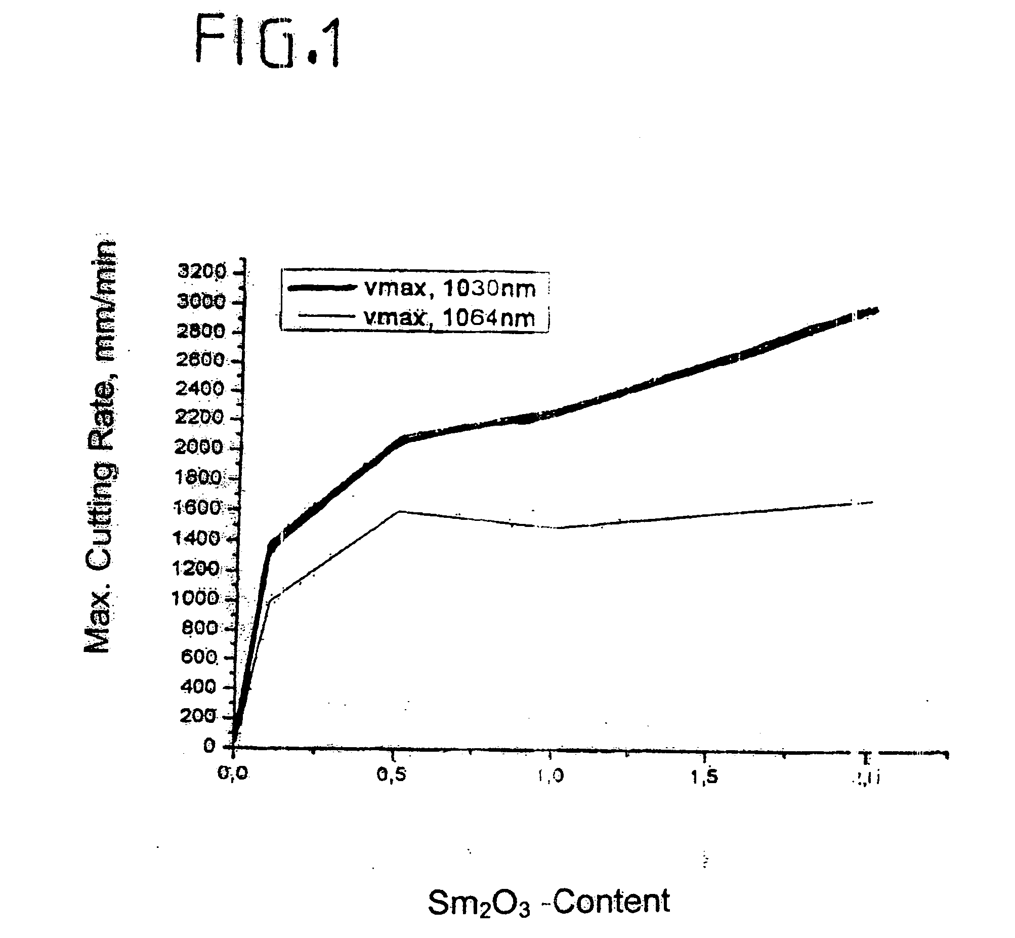
The present invention provides a thin flat glass for display purposes that can be more rapidly heated up with a Nd:YAG laser and cut more quickly than previous versions. This is achieved by adding an additive ingredient that effectively absorbs radiation of a wavelength of 1.064 μm, which allows for faster heating of the cutting line. The additive ingredient can be a small amount of samarium oxide, which is added to the glass to improve its cutting speed. The use of samarium oxide as an auxiliary agent in flat glass for improving its cutting properties with a Nd:YAG laser has been previously described in the patent text. The flat glass used in the invention is an alkali-free borosilicate glass with a specific composition. The invention provides a solution for improving the cutting of alkali-free flat glass.

Problems solved by technology

In this method particles (splitter) are released from the surface, which can deposit on the glass and which can lead e.g. to scratches there.
Furthermore the micro-cracks produced by the scoring at the cut edge lead to a reduction in mechanical structural strength or to mechanical stresses, i.e. to an increased danger of breaking of the cut structure.
Thermal stresses, which are produced in the glass by an immediate cooling, lead to cracking of the glass sheet at the desired positions.
However the absorbed radiation energy can be multiplied by an optical system, which reflects the beam many times through the glass, which leads to local heating and expansion.
The heating up of the cut edge however takes an increased amount of time, which limits the process times for cutting and thus the efficiency of the manufacturing method in a disadvantageous manner.

Method used


Image

  • Thin flat glass for display purposes and method of cutting the thin flat glass into display sheets
  • Thin flat glass for display purposes and method of cutting the thin flat glass into display sheets
  • Thin flat glass for display purposes and method of cutting the thin flat glass into display sheets

Examples


Embodiment Construction

[0027] The borosilicate glasses were made by melting the raw materials with the compositions listed in Table I at a temperature of 1620° C. in a gas-fired quartz vessel for 120 minutes. The commercially obtained raw materials had the compositions listed in Table I, and were essentially alkali metal free apart from the inevitably present impurities. The melt was refined for 90 minutes at the temperature of 1620° C. and then poured into an inductively heated platinum crucible or vessel. The melt was stirred for 45 minutes at 1520° C. in order to homogenize it The poured glass block was cooled at 730° C. at a rate of 20° C. / min.

TABLE IFLAT GLASS COMPOSITIONS AND PROPERTIESExample 1Example 2Example 3Example 4SiO261.1560.1560.1560.15B2O39.759.759.759.75Al2O314.9014.9014.9014.90MgO2.802.802.802.80CaO5.005.005.005.00BaO3.203.203.203.20TiO22.001.501.501.00CeO2—0.50—0.50MoO3——0.500.50Sm2O31.00—2.001.00Yb2O32.001.00SnO20.200.200.200.20L*96.596.596.396.4a*−0.1−0.1−0.1−0.2b*0.70.81.11.1C* (Ch...


PUM

PropertyMeasurementUnit
thicknessaaaaaaaaaa
wavelengthaaaaaaaaaa
thicknessesaaaaaaaaaa

Abstract

To improve the cutting properties, especially the cutting rate, of thin flat glass by means of a laser cutting beam from a Nd:YAG solid-state laser, the flat glass is provided during its manufacture with at least one additive ingredient that effectively absorbs radiation at a wavelength of 1.064 μm. Preferably the additive ingredient is preferably samarium oxide (Sm2O3). A method of cutting through a flat glass sheet whose composition contains at least one additive ingredient that absorbs a significant amount of radiation at a wavelength of 1.064 μm, which includes cutting the flat glass sheet with the focused radiation of a Nd:YAG laser, is also part of the present invention.

Description

CROSS-REFERENCE [0001] The invention described and claimed hereinbelow is also described, at least in part, in German Patent Application DE 10 2005 031 599.2-46 filed on Jul. 6, 2005 and, at least in part, in another German Patent Application filed on Jun. 16, 2006. The foregoing German Patent Applications provide the basis for a claim of priority of invention of the invention described hereinbelow based on 35 U.S.C. 119 and their subject matter is hereby incorporated by reference. BACKGROUND OF THE INVENTION [0002] 1. The Field of the Invention [0003] The present invention relates to a thin flat glass for display purposes with improved cutting properties for cutting by means of a laser beam, especially by a cutting beam from a ND:YAG laser. The invention also relates to a method for cutting the thin flat glass into display sheets. [0004] 2. Related Art [0005] Thin flat glass sheets of the greatest variety of sizes and configurations are required for numerous applications. Mobile ph...

Claims


Application Information

Patent Timeline
Patent Type & Authority Applications(United States)
IPC IPC(8): B23K26/38B23K26/00B29C35/08B23K26/40
CPCC03C3/095C03B33/091C03C4/08C03B33/09B23K26/402
Inventor BRIX, PETERZACHAU, THILOBEIER, WOLFRAMLIEBALD, RAINERSPRENGER, DIRK
Owner SCHOTT AG
Learn More