Digital transmitters for wireless communication

Active Publication Date: 2007-07-12
QUALCOMM INC
View PDF16 Cites 77 Cited by
  • Summary
  • Abstract
  • Description
  • Claims
  • Application Information

AI Technical Summary

Benefits of technology

[0008] A fourth circuit block (which may comprise one or more exclusive-OR gates or an amplifier with multiple gain states) generates a digitally modulated signal based on the envelope signal and the phase modulated signal. A fifth circuit block (which may comprise a class D amp

Problems solved by technology

These analog circuit blocks may be difficult to design and may also be susceptible to performance degradation due to component mismatches and tolerances.
Furthermor

Method used


Image

  • Digital transmitters for wireless communication
  • Digital transmitters for wireless communication
  • Digital transmitters for wireless communication

Examples


Embodiment Construction

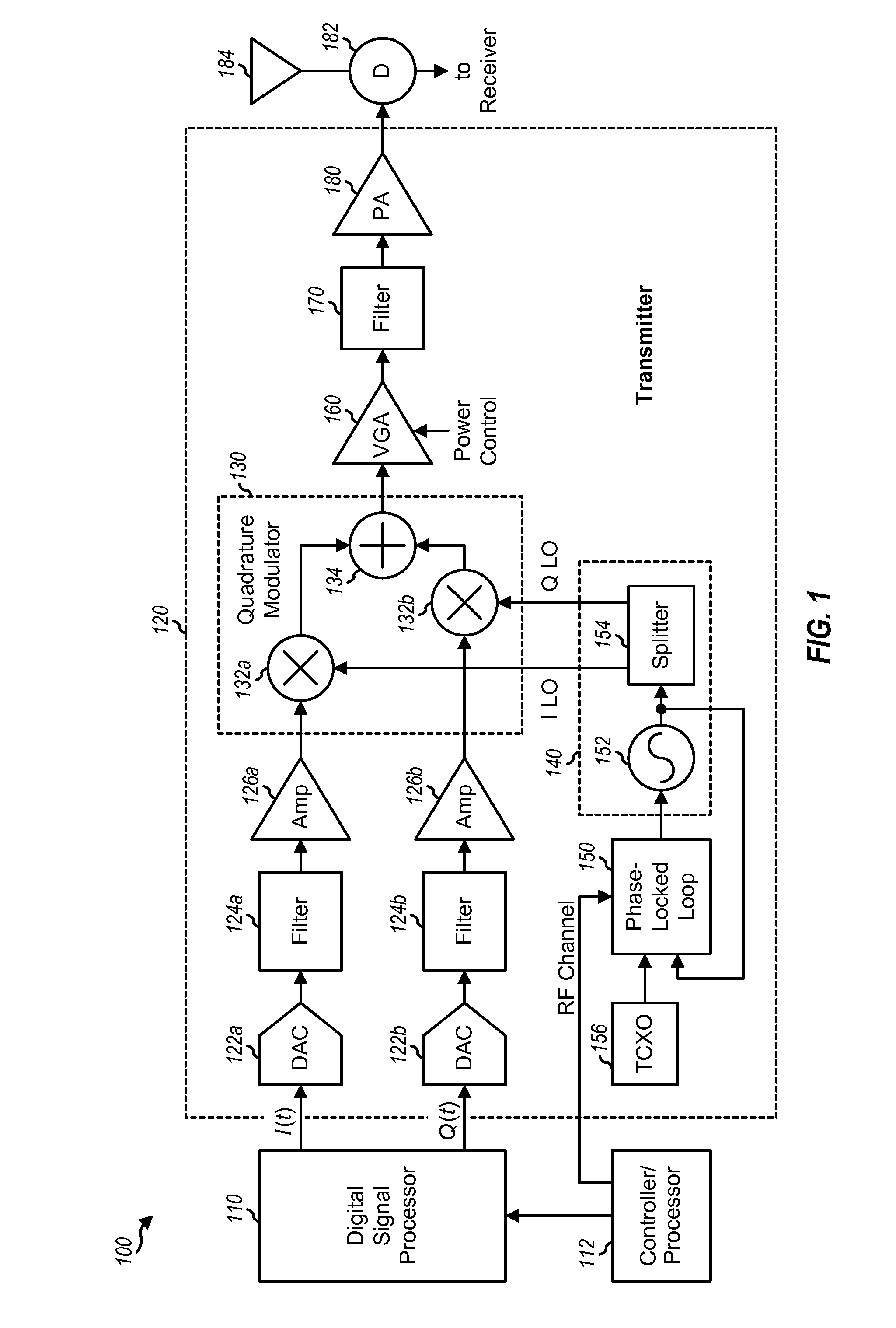
[0022]FIG. 1 shows a block diagram of a wireless device 100 with an analog transmitter 120. A digital signal processor (DSP) 110 processes traffic data to be transmitted and provides inphase (I) and quadrature (Q) data streams, which are denoted as I(t) and Q(t) signals, respectively, where t denotes sample period. Within transmitter 120, the I data stream is converted to an I analog signal by a DAC 122a, filtered by a filter 124a to remove images caused by the digital-to-analog conversion, and amplified by an amplifier (Amp) 126a to generate an I modulating signal. Similarly, the Q data stream is converted to a Q analog signal by a DAC 122b, filtered by a filter 124b, and amplified by an amplifier 126b to generate a Q modulating signal.

[0023] A quadrature modulator 130 receives the I and Q modulating signals from amplifiers 126a and 126b, respectively, and I and Q LO signals from an LO generator 140. The I and Q LO signals are 90 degrees out of phase with each other. Within quadra...


PUM


Abstract

Digital transmitters having improved characteristics are described. In one design of a digital transmitter, a first circuit block receives inphase and quadrature signals, performs conversion from Cartesian to polar coordinates, and generates magnitude and phase signals. A second circuit block (which may include a delta-sigma modulator or a digital filter) generates an envelope signal based on the magnitude signal. A third circuit block generates a phase modulated signal based on the phase signal. The third circuit block may include a phase modulating phase locked loop (PLL), a voltage controlled oscillator (VCO), a saturating buffer, and so on. A fourth circuit block (which may include one or more exclusive-OR gates or an amplifier with multiple gain states) generates a digitally modulated signal based on the envelope signal and the phase modulated signal. A fifth circuit block (which may include a class D amplifier and/or a power amplifier) amplifies the digitally modulated signal and generates an RF output signal.

Description

[0001] The present Application for Patent claims priority to Provisional Application No. 60 / 737,898 entitled “DIGITAL TRANSMITTER FOR WIRELESS COMMUNICATION” filed Nov. 18, 2005, and assigned to the assignee hereof and hereby expressly incorporated by reference herein.BACKGROUND [0002] I. Field [0003] The present disclosure relates generally to electronic circuits, and more specifically to a transmitter for wireless communication. [0004] II. Background [0005] In a wireless communication system, a wireless device often digitally processes traffic data to generate data samples. A transmitter within the wireless device typically converts the data samples to analog signals, filters and amplifies the analog signals, and modulates a local oscillator (LO) signal with the amplified analog signals to generate a modulated signal. The transmitter further filters and amplifies the modulated signal to generate a radio frequency (RF) output signal that is suitable for transmission via a wireless ...

Claims


Application Information

Patent Timeline
IPC IPC(8): H04L27/00
CPCH03C5/00H03D13/00H03F1/0205H03F3/217H03F3/245H04L27/361H03F2200/331H03F2200/336H03F2200/451H03F2200/456H03F2200/321H04L27/36
Inventor SAHOTA, GURKANWAL S.
Owner QUALCOMM INC
Why Eureka
Try Eureka