Optical interface for local MRI coils

a local coil and optical interface technology, applied in the field of magnetic resonance imaging, can solve the problems of inflexibility, large shielded cables passing from the local coil to the termination box, and a difficult electrical environment of the mri machine, and achieve the effect of costing the modulation circuitry

Inactive Publication Date: 2007-07-19
INVIVO CORP
View PDF8 Cites 21 Cited by
  • Summary
  • Abstract
  • Description
  • Claims
  • Application Information

AI Technical Summary

Benefits of technology

[0013] The present inventors have recognized that the above obstacles to optical transmission of NMR signals can be moderated by a detachable optical cable system integrated with an optical modulator (and possibly a demodulator) so that connections between the optical cable and local coil may be made using a conventional electrical connector. In this way, the cost of the modulation circuitry can be shared among a number of coils, optical connectors are eliminated, and if the electrical connector is correctly chosen, the optical cable can be used for both new and legacy coils.
[0017] It is yet another object of at least one embodiment of the invention to overcome the problem of decreased signal-to-noise ratio caused by current optical connectors. By integrating the modulator with the cable, electrical connectors can be used to disconnect the cable from the local coil and MRI machine, reducing or avoiding the need for optical connectors.
[0019] It is thus another object of at least one embodiment of the invention to provide a migration path to optically enabled local coils by providing a cable system that may work with conventional MRI machines and with legacy local coils.
[0023] Thus it is another object of at least one embodiment of the invention to wholly eliminate electrical shields that reduce flexibility of the cable, and to thereby wholly eliminate shield currents such as increase electrical interference and produce undesirable heating of the patient.
[0025] It is thus another object of at least one embodiment of the invention to provide for a low cost version of the optical transmission cable that does not require optical transmission of substantial power but which may use standard techniques to block shield currents on DC conductors.

Problems solved by technology

The area around the operating MRI machine represents a difficult electrical environment for connecting a local coil to the MRI acquisition circuitry, principally with respect to establishing a good radio frequency ground.
The switched fields used during the imaging process can promote high shield currents on the shield that may cause heating and possible risk to the patient.
The shielded cables passing from the local coils to the termination box are relatively bulky and inflexible, in part, as a result of the necessary physical separation required between the patient and currents in the shield (normally enforced by a thick insulator), and the inherent stiffness of the cable conductors.
This later problem is exacerbated for multi-channel coils which employ separate conductors for each channel.
The inflexibility and bulk of these shielded cables can cause storage problems when multiple coils must be stored on-site, for example, in the limited space of the MRI room.
However, this approach faces a number of practical problems.
The first is the high cost of optical modulation circuitry suitable to provide high signal-to-noise transmission of the NMR signal, a cost that is multiplied by the number of channels of the local coil.
Optical connectors allowing connecting and disconnecting of the optical fiber system from the MRI machine are currently inadequate for use in the MRI environment and introduce unacceptable signal noise resulting from the extreme sensitivity of fiber connections to vibration induced changes in alignment.
One final problem with optical transmission of NMR signals from local coils is the large installed base of conventional local coils and MRI machines that are not “optically enabled”, accepting only electrical rather than optical signals.
Such systems present an obstacle to large-scale adoption of an optical transmission system which initially would be suitable for only a small market of machines.

Method used


Image

  • Optical interface for local MRI coils
  • Optical interface for local MRI coils
  • Optical interface for local MRI coils

Examples


Embodiment Construction

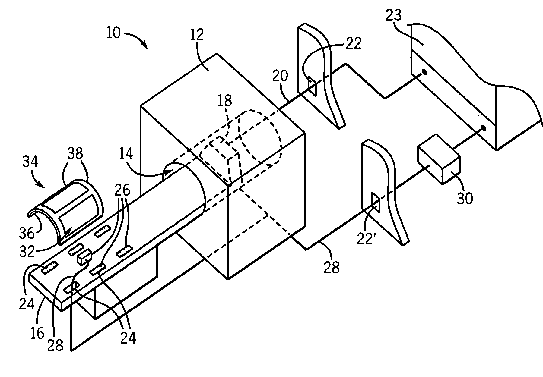
[0032] Referring now to FIG. 1, an MRI machine 10 may include a magnet assembly 12 providing a homogenous polarizing magnetic field within a bore 14 of the magnet assembly 12.

[0033] The bore 14 may receive a patient table 16 for supporting a patient thereupon, the patient table 16 movable through the bore 14 during the examination process. The table 16 may include a termination box 18 at one end to which signals from local coils may be connected by means of connectors on the termination box 18 (not shown).

[0034] The termination box 18 communicates by means of shielded electrical cable 20 through a penetrator 22 in a shielded wall of the MRI room to an MRI processing unit 23, the latter which receives the NMR signals and reconstructs them into an image. Shielded electrical cable 20 may also carry transmit signals in the opposite direction, the transmit signals being an RF pulse transmitted to some local coils that provide transmitting as well as receiving capabilities as will be de...


PUM


Abstract

An implementation of an optical transmission path for NMR signals from local coils in magnetic resonance imaging employs a photomodulator that may be incorporated into a connecting optical cable to be shared among multiple local coils and to provide for connection and disconnection at an electrical interface eliminating the need for optical connectors.

Description

STATEMENT REGARDING FEDERALLY SPONSORED RESEARCH OR DEVELOPMENT [0001] Not applicable CROSS-REFERENCE TO RELATED APPLICATIONS [0002] Not applicable BACKGROUND OF THE INVENTION [0003] The present invention relates to magnetic resonance imaging (MRI) and in particular to an interface for connecting local coils used in MRI imaging to an MRI machine. [0004] Magnetic resonance imaging can provide sophisticated images of the human body by detecting faint nuclear magnetic resonance (“NMR”) signals, primarily from concentrations of hydrogen protons in the tissues of the body. In MRI, a patient is located in a strong, polarizing, magnetic field and hydrogen protons of the patient's tissues are excited into precession with a radio frequency (“RF”) pulse. A series of applied gradient magnetic fields are switched on and off to spatially encode the precessing protons by phase and frequency. A sensitive antenna is then used to detect the NMR signals which are reconstructed into images. [0005] MRI...

Claims


Application Information

Patent Timeline
Patent Type & Authority Applications(United States)
IPC IPC(8): G01V3/00
CPCG01R33/3692
Inventor JEVTIC, JOVANTATUM, NUNEZ
Owner INVIVO CORP
Why Eureka
Try Eureka