Method for catalytically cracking waste plastics and apparatus for catalytically cracking waste plastics

a technology of catalytic cracking and waste plastics, applied in the field of catalytic cracking waste plastics and catalytic cracking apparatus, can solve the problems of complex apparatus structure, high processing cost, poor efficiency of decomposition reaction, etc., and achieve the effect of improving productivity

Inactive Publication Date: 2007-07-26
KITAKYUSHU FOUND FOR THE ADVANCEMENT OF IND
View PDF6 Cites 54 Cited by
  • Summary
  • Abstract
  • Description
  • Claims
  • Application Information

AI Technical Summary

Benefits of technology

[0123](1) an apparatus for catalytically cracking waste plastics can be provided in which the operation can be conducted continuously with a simple apparatus to attain a remarkable improvement in productivity, since the reaction vessel is a rotary kiln-type reaction vessel and waste plastics are loaded continuously, agitated by rolling motion, and brought into contact with the FCC catalyst to effect decomposition and gasification.

Problems solved by technology

However, the above-described conventional technology has the following problems.
Namely, since the technology is a multiple stage process in which sands are used as a fluid vehicle in all the steps, an apparatus is complicated in structure to raise the processing cost, which is a problem.
The efficiency of decomposition reaction is poor, and net yield of oil fractions is low in decomposing cracked gas to petroleum, which is also a problem.
(2) Hydrogen chloride is carried over from a dechlorination step of waste plastics to a thermal decomposition step, chlorine is left as organic chlorine content at 1000 ppm or more with respect to the thus obtained oil fraction, which is a problem.
on thermal decomposition, and it may easily cause carbonization when mixed with high-temperature sands, thereby generating a great amount of decomposed residue, which is also a problem.

Method used


Image

  • Method for catalytically cracking waste plastics and apparatus for catalytically cracking waste plastics
  • Method for catalytically cracking waste plastics and apparatus for catalytically cracking waste plastics
  • Method for catalytically cracking waste plastics and apparatus for catalytically cracking waste plastics

Examples


first embodiment

The First Embodiment

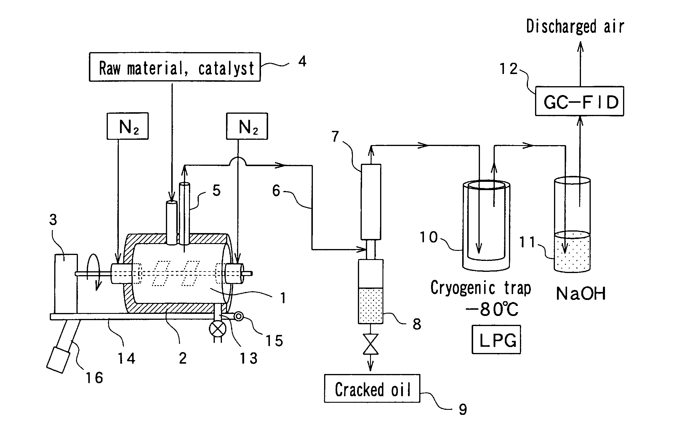
[0185]FIG.1 is a schematic view of an apparatus for catalytically cracking waste plastics according to the first embodiment of the present invention.

[0186]In FIG. 1, the numeral 1 denotes a horizontal-type reaction vessel shaped in a cylindrical form and having a heater 2 as heating means and a rotary-vane type agitator 3 as agitating means. The heater 2 is used to heat granular FCC waste catalysts loaded from a material port 4 up to a temperature range from 300° C. to 500° C., preferably from 400° C. to 480° C. and more preferably from 410° C. to 430° C. In this embodiment, the heater 2 is such a heater that can be easily controlled for temperatures, for example, an electric heater. Waste plastics which are finely degraded into granules to flakes are loaded into granular FCC waste catalysts heated to a high temperature inside the reaction vessel 1 and mixed and agitated by the agitator 3 to dredge the waste plastics with the high-temperature granular FCC waste c...

experiment 1

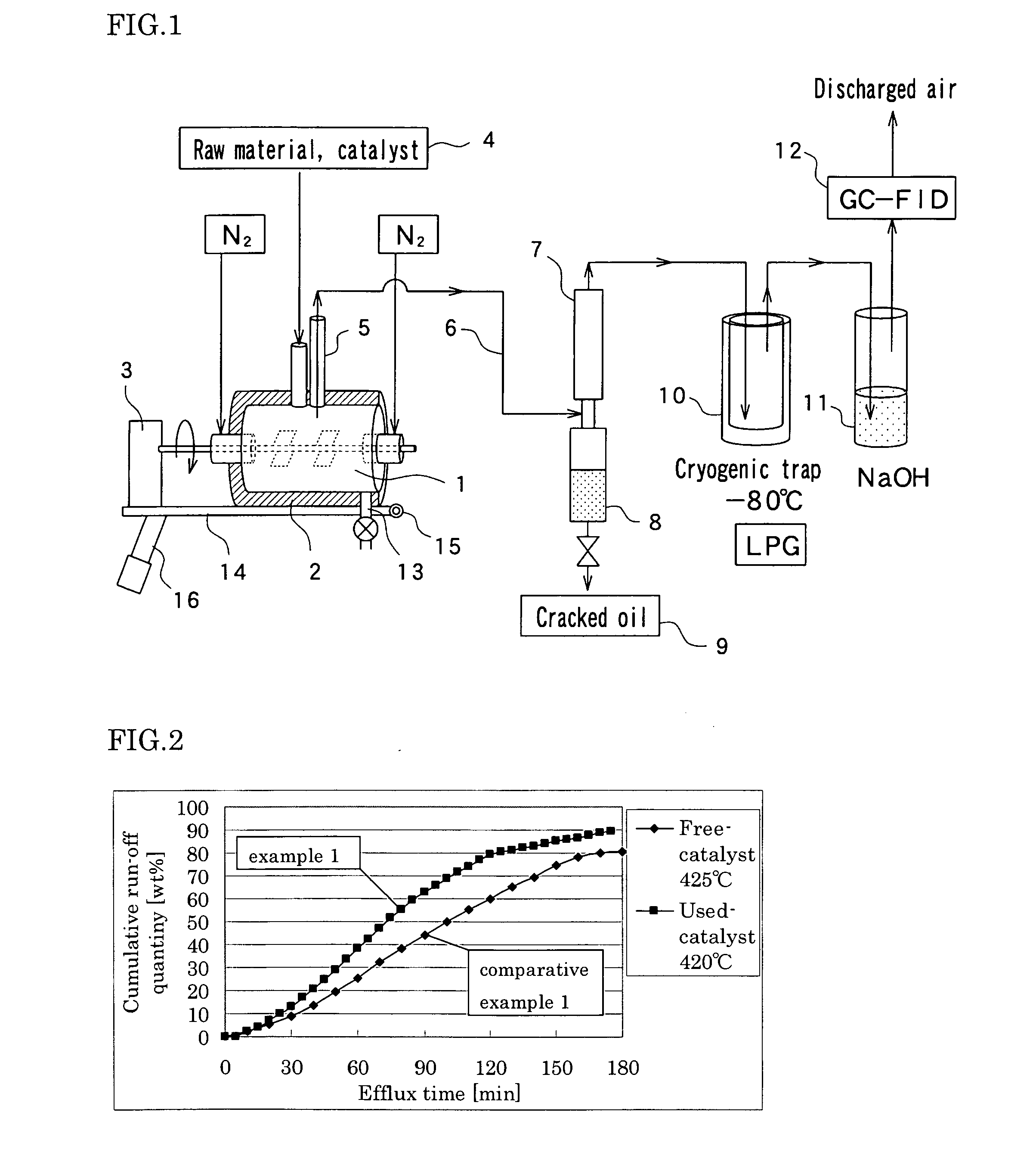
[0194]The catalytically cracking apparatus described in the first embodiment 1 is used to carry out the following processes, namely, 10 g of granular FCC waste catalyst is heated to 420° C. by actuating a heater 2 inside a reaction vessel 1, 75 g of granular to flake-shaped polyethylene (PE) is loaded into the high-temperature granular FCC waste catalyst from a material port 4, an agitator 3 is rotated at 50 rpm, the granular FCC waste catalyst is mixed and agitated with granular to flake-shaped polyethylene (PE), the polyethylene (PE) is dredged with the high-temperature granular FCC waste catalyst, thereby facilitating heating / decomposition reactions. The decomposition reaction is set to proceed at 420° C. under an atmospheric pressure. Cracked gas is sent into a cooling mechanism 7, with N2 gas (100 mL / min) being used as a carrier, then, cooled and liquefied to obtain oil fractions.

[0195]FIG. 2 shows a relationship between the efflux time and the cumulative run-off quantity (weig...

experiment 2

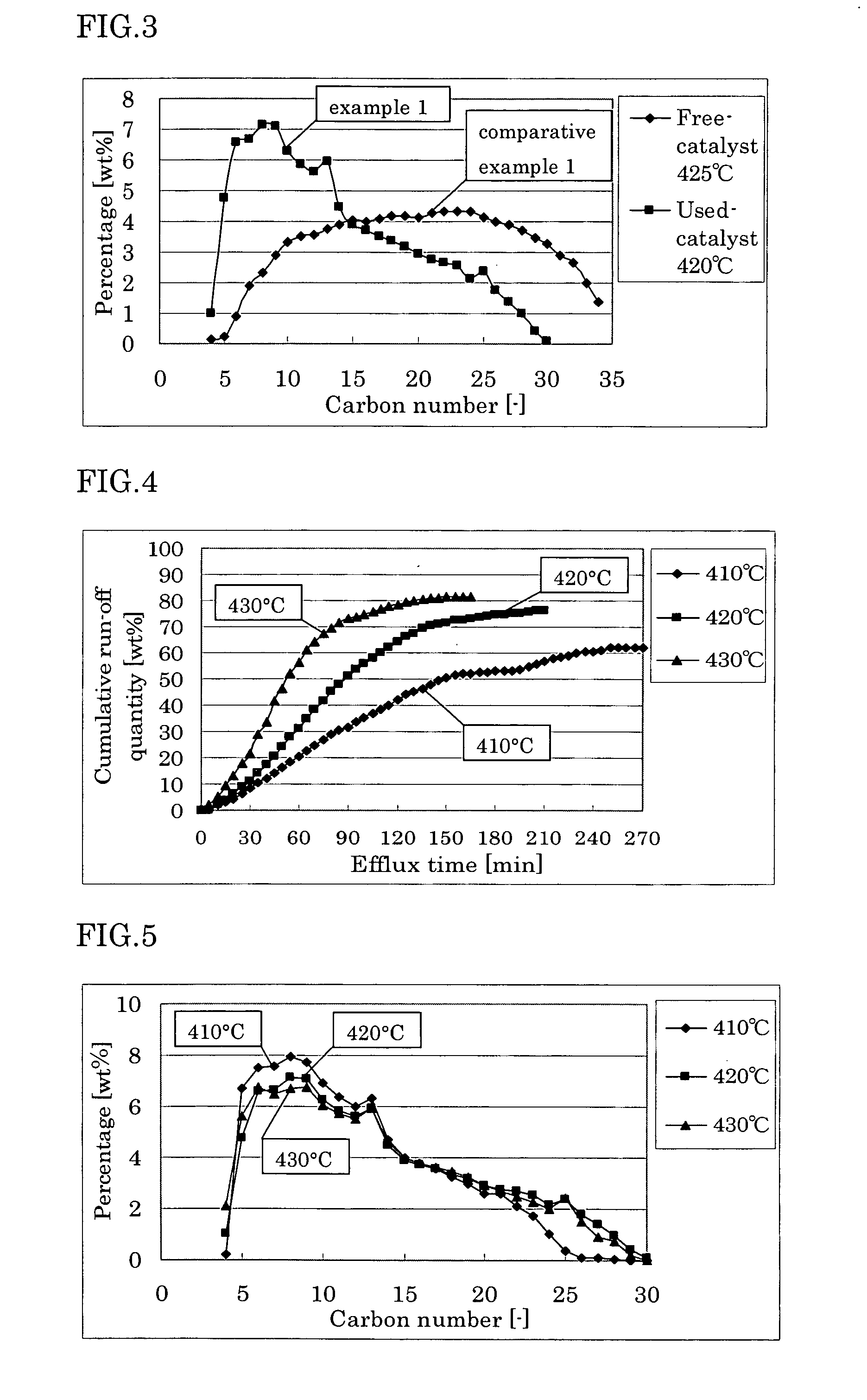
[0199]Evaluation is made for a relationship between the efflux time and the cumulative run-off quantity (weight %) of decomposition products, a carbon number distribution of cracked oil and a quantity of cracked gas produced under the conditions the same as those in Experiment 1 except that the reaction temperature is set at three levels, namely, 410° C., 420° C. and 430° C. It is noted that the cumulative run-off quantity (weight %) of decomposition products and the carbon number distribution of cracked oil are determined similarly as in Example 1.

[0200]FIG. 4 shows a relationship between the efflux time and the cumulative run-off quantity (weight %) of decomposition products.

[0201]As apparent from FIG. 4, cracked oil is obtained at a higher yield according to a higher reaction temperature, and the cracked oil flows out at a greater speed. Further, as apparent from FIG. 6, gas is produced at an increased quantity, and decomposition takes place more easily. However, as apparent from...


PUM

PropertyMeasurementUnit
temperatureaaaaaaaaaa

Abstract

To provide a method for catalytically cracking waste plastics wherein the efficiency in decomposition is high; even polyethylene composed of linear chain molecules difficult in decomposition is decomposable at a low temperature and decomposed residue is hardly produced; the process is simple since dechlorination can be achieved at the same time with catalytically cracking waste plastics in one reaction vessel; and oil fractions can be recovered at 50% or more on a net yield basis. The method for catalytically cracking waste plastics of the present invention has a constitution in which waste plastics are loaded as a raw material into a granular FCC catalyst heated to a temperature range from 350° C. to 500° C. inside a reaction vessel, thereby decomposing and gasifying the waste plastics in contact with the FCC catalyst.

Description

TECHNICAL FIELD[0001]The present invention relates to a method for thermally decomposing waste plastics, namely, waste materials of plastics such as polyethylene (PE), polypropylene (PP), polystyrene (PS) or polyethylene terephthalate (PET) and waste plastics having a resin, for example, polyvinylchloride (PVC), in which chlorine is contained as a composition, and an apparatus therefor.BACKGROUND OF THE INVENTION[0002]Currently, in Japan, about 10 million tons of plastics are being discarded annually as industrial waste or general waste, about 55% of which are used effectively. Most of these waste plastics are used as fuels for generating electricity or other heat sources, and not substantially recycled as chemical materials. An unused portion of these waste plastics is disposed of in landfills or subjected to incineration disposal. However, available landfills are becoming tighter year by year and there is a fear of generating dioxins on incineration when resins are mixed such as p...

Claims


Application Information

Patent Timeline
Patent Type & Authority Applications(United States)
IPC IPC(8): C10G1/10B01J8/10
CPCB01J8/0055C10G2300/4006B01J8/1836B01J19/0066B01J19/18B01J2208/00407B01J2208/00415B01J2208/00504B01J2208/0053B01J2208/00557B01J2208/025B01J2219/00779B01J2219/182B01J2219/1943C10G1/10C10G2300/1003B01J8/10
Inventor FUJIMOTO, KAORULI, XIAOHONG
Owner KITAKYUSHU FOUND FOR THE ADVANCEMENT OF IND
Why Eureka
Try Eureka