Differential amplifier and digital-to-analog converter

a technology of digital to analog converter and differential amplifier, which is applied in the direction of analogue/digital conversion, code conversion, amplifier modification to reduce noise influence, etc., can solve the problem that the configuration cannot meet the demand for high-speed operation, and achieve high-speed operation, suppress the influence of power supply noise, and reduce the input capacitance

Inactive Publication Date: 2007-08-02
NEC CORP
View PDF3 Cites 2 Cited by
  • Summary
  • Abstract
  • Description
  • Claims
  • Application Information

AI Technical Summary

Benefits of technology

[0019]Accordingly, it is an object of the present invention to suppress the influences of power supply noise, signal noise, and switch noise in a differential amplifier that operationally amplifies and outputs voltages according to a plurality of input reference voltages serially supplied and provide a differential amplifier capable of high-speed operation.
[0020]It is another object of the present invention to provide a differential amplifier that substantially reduces its input capacitance.
[0021]It is a further object of the present invention to provide a digital-to-analog converter circuit, a data driver, and a display device, comprising a differential amplifier that functions as an operational amplifier capable of outputting many levels of analog voltages from few number of input reference voltages. A yet another object of the present invention is to provide a digital-to-analog converter circuit, a data driver, and a display device, comprising a differential amplifier capable of reducing the number of decoder elements thereby reducing its area.

Problems solved by technology

In other words, this configuration cannot meet the demand for high-speed operation.

Method used


Image

  • Differential amplifier and digital-to-analog converter
  • Differential amplifier and digital-to-analog converter
  • Differential amplifier and digital-to-analog converter

Examples


example 1

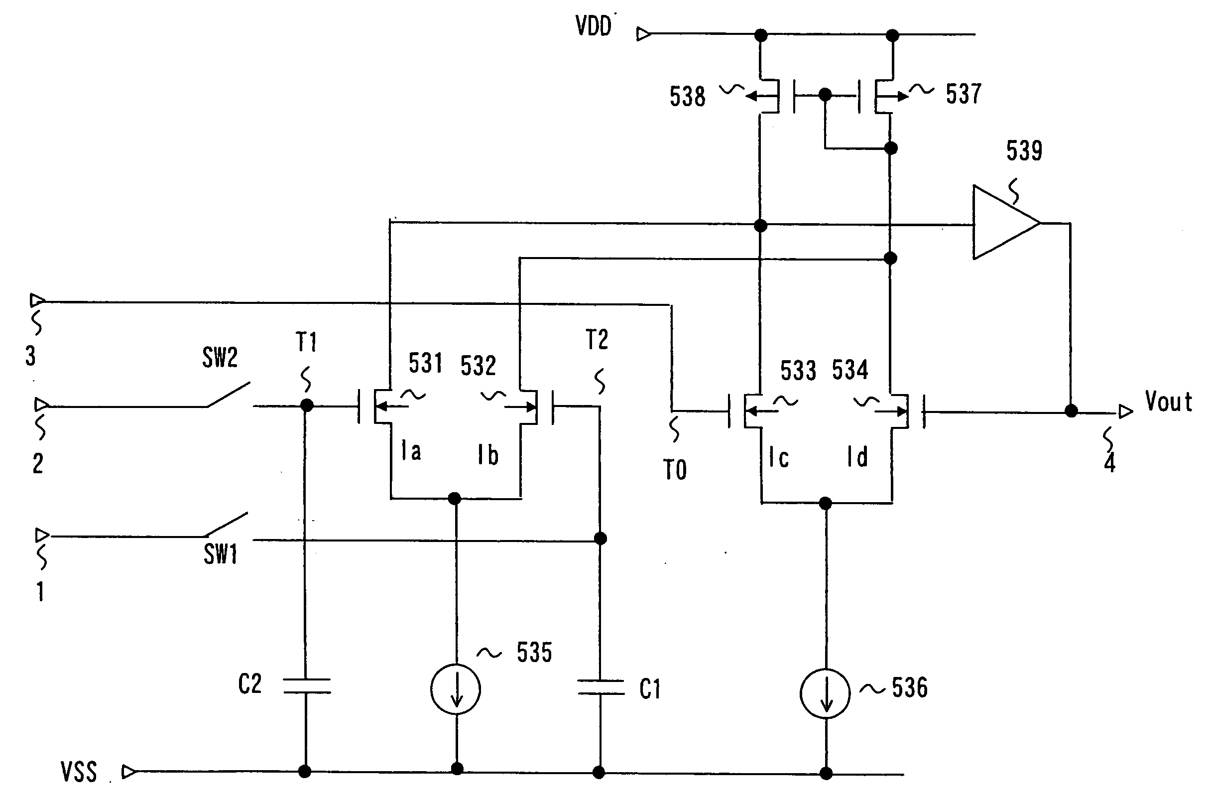
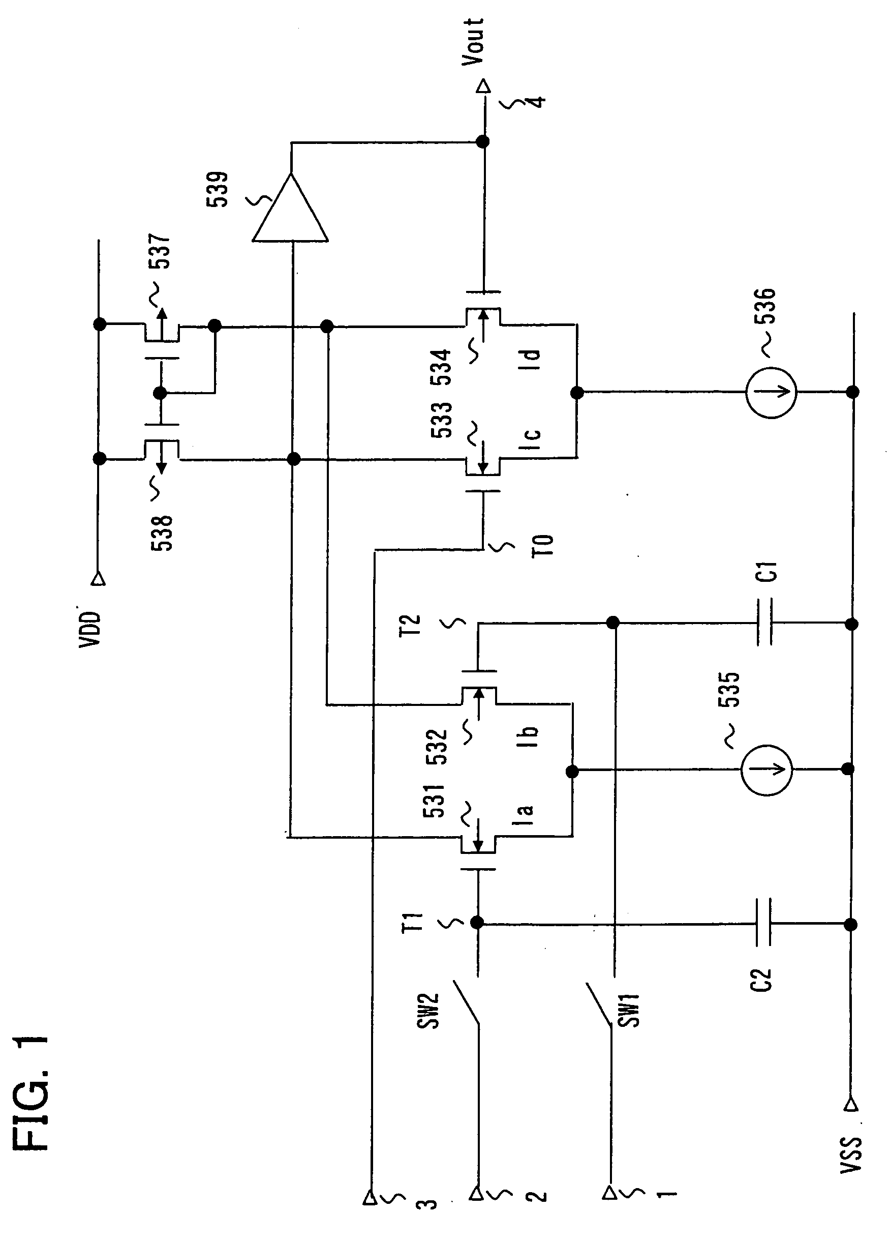
[0062]FIG. 1 is a drawing showing the configuration of a differential amplifier of a first example of the present invention. Referring to FIG. 1, the differential amplifier of this example comprises NMOS transistors 532 and 531 constituting the first differential pair (531 and 532), and having their sources connected in common and their gates respectively connected to the terminals 1 and 2 via switches SW1 and SW2, a constant current source 535 connected between the common source of the NMOS transistors 532 and 531 and the low potential side power supply VSS, NMOS transistors 533 and 534 constituting the second differential pair (533 and 534), and having the sources connected in common and the gates respectively connected to the terminal 3 and the output terminal 4, the constant current source 536 connected between the common source of the NMOS transistors 533 and 534 and the low potential side power supply VSS, a PMOS transistor 537 having the source connected to a high potential s...

example 2

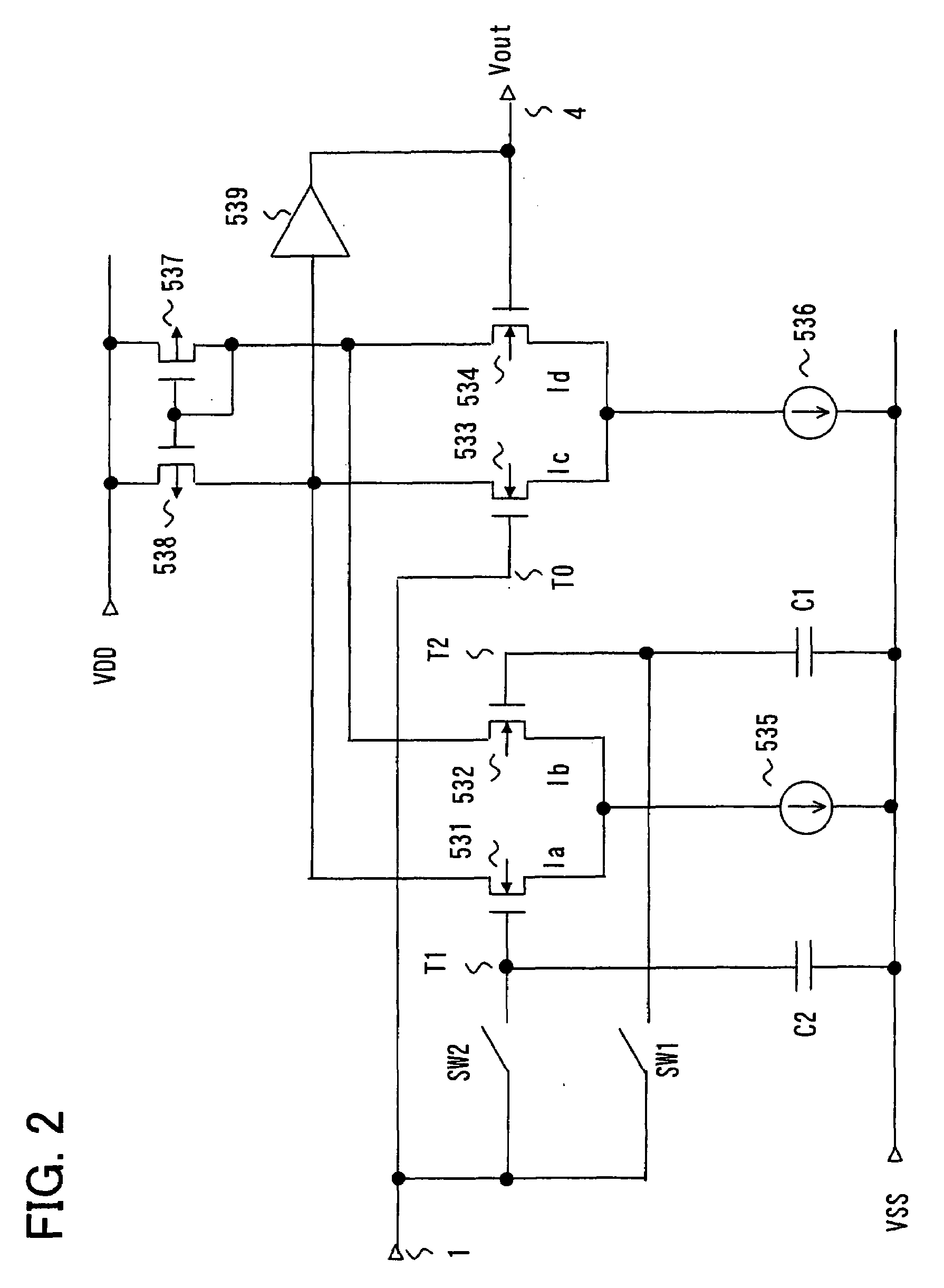
[0084]Next, a second example of the present invention will be described. FIG. 2 is a drawing showing the configuration of the second example of the present invention. Referring to FIG. 2, this example has the same configuration as the differential amplifier shown in FIG. 1 except that the terminals 1, 2, and 3 are made into one common terminal 1. Note that the terminal T0 is directly connected to the terminal 1. One ends of the switches SW1 and SW2 are respectively connected to the input pair (the terminals T2 and T1) of the differential pair (531 and 532), and the other ends are connected in common to the terminal 1. Other than that, the configuration of this example is identical to that of the first example described above.

[0085]In this example, the voltages received by the terminals T0, T1, and T2 are supplied serially from the terminal 1. The switches SW1 and SW2 are switch-controlled from ON to OFF in the order of the voltages supplied to the terminals T2 and T1, and the voltag...

example 3

[0096]Next, a third example of the present invention will be described. FIG. 5 is a drawing showing the configuration of the third example of the present invention. Referring to FIG. 5, this example further comprises a switch SW3 connected between the output terminal 4 and the terminal T2 and a switch SW4 connected between the output terminal 4 and the terminal T1, in addition to the configuration of the differential amplifier shown in FIG. 2. Other than that, the configuration of this example is identical to the configuration shown in FIG. 2. This example differs from the second example described above in how the switches are controlled.

[0097]FIG. 6 is a drawing for explaining the operation of the differential amplifier shown in FIG. 5, and it shows the order in which the voltages V(T0), V(T1), and V(T2), eventually received by the terminals T0, T1, and T2 of the differential pairs, are supplied from the input terminal 1 during a data period and how the switches SW1, SW2, and SW3 a...


PUM


Abstract

A differential amplifier comprises first, second, and third input terminals (1, 2, and 3), output terminal (4), first and second differential pairs (531 and 532) (533 and 534) driven by a corresponding current source and having output pairs commonly connected to load circuits (537 and 538), and an amplifier stage (539) having input end connected to at least one of the common connection points of the load circuits and output pairs of the first and second differential pairs and output end connected to output terminal. Input pair of second differential pair receives a signal from third input terminal and a feedback signal from output terminal. First and second switches (SW1 and SW2) are provided between the input pair of the first differential pair and the first and second input terminals (1 and 2), and first and second capacitors (C1 and C2) connected between each connection point of the input pair of the first differential pair and the first and second switches (SW1 and SW2) and a reference voltage terminal are provided. The first, second and third input terminals (1, 2, and 3) may be combined into one terminal to which voltages are serially supplied. It avoids the influence of power supply/signal noise and switch noise, and provides operational output from a plurality of input reference voltages.

Description

FIELD OF THE INVENTION[0001]The present invention relates to a differential amplifier and a digital-to-analog converter, and particularly to a differential amplifier, a digital-to-analog converter, and a data driver comprising the digital-to-analog converter suitable for use as a driver for a display device.BACKGROUND OF THE INVENTION[0002]In recent years, liquid crystal displays (LCD), characterized by their thinness, light-weightiness, and low power consumption, have been widely spread, and used for displays of mobile devices such as mobile phones, cellular phones, PDAs (personal digital assistants), and notebook computers. However, as technologies to enlarge screens of liquid crystal displays and support moving pictures advance, liquid crystal displays are used for not only mobile devices, but also stationary large-screen display devices and large-screen LCD televisions. As such liquid crystal display devices, active matrix LCD devices allowing high definition display are current...

Claims


Application Information

Patent Timeline
Patent Type & Authority Applications(United States)
IPC IPC(8): H03F1/02
CPCH03F1/26H03F3/45183H03M1/765H03F2203/45548H03F2203/45616H03F2200/372
Inventor TSUCHI, HIROSHIIRIGUCHI, MASAO
Owner NEC CORP
Why Eureka
Try Eureka