
Optical access network system

a network system and optical access technology, applied in the field of optical access network systems, can solve the problems of high equipment costs, difficult to obtain a/d converters and digital multipliers capable of operating at such a high speed, and the inability to receive signals correctly by the onu, etc., to achieve the effect of reducing equipment costs

Inactive Publication Date: 2007-08-02
OKI ELECTRIC IND CO LTD
View PDF28 Cites 12 Cited by
  • Summary
  • Abstract
  • Description
  • Claims
  • Application Information

AI Technical Summary

Benefits of technology

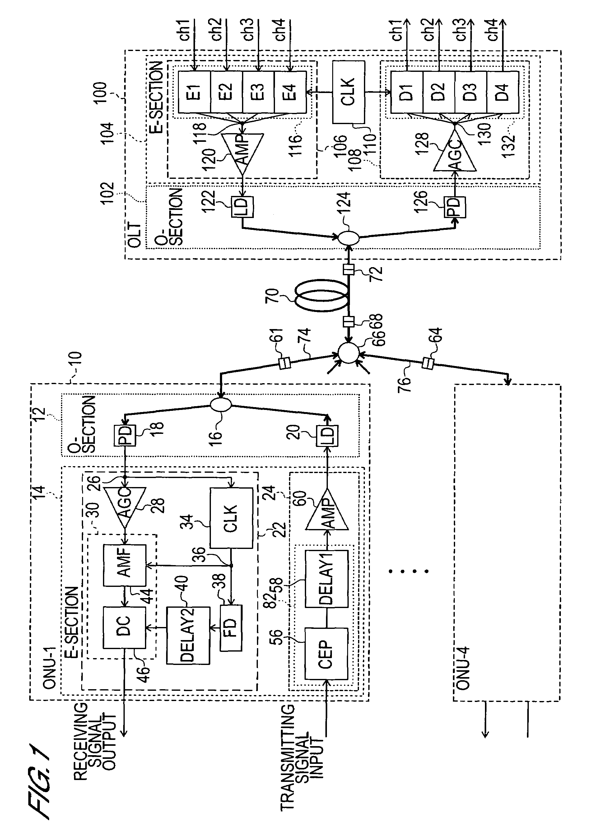
[0033]Furthermore, because the transmitting signal processing section comprises a delay circuit for adjusting the phase of the encoded transmitting signal, the problem of reflection noise being mixed with the transmitting signal that occurs in the optical connector and so forth for the connection with the optical (de)multiplexer provided in the optical transmitting line can be prevented from occurring. Hence, there is no need to use light of different wavelengths for the uplink and downlink signals and there is no need to increase the required number of light components of different wavelengths.
[0045]As described earlier, the optical access network system of the second invention provides a PON-based optical access network system in which the S / N ratio of the receiving signal does not drop even when a reflected light component from the optical connector used to connect the ONU and star coupler is mixed with the receiving signal of the ONU. Accordingly, a low-cost optical connector with a large reflected light component can be used to connect the star coupler and ONU, which makes a large contribution toward reducing equipment costs.

Problems solved by technology

In order to make the wavelength interval narrow in this manner, light-source wavelength stability is required and high equipment costs are required in order to secure this stability.
However, executing an optical access method using PON that includes a step of encoding and multiplying a transmitted electrical signal, a step of up-converting the signal to an RF signal, and an A / D conversion step by means of an A / D converter produces the following problems.
In their current form, an A / D converter and digital multiplier capable of operating at such a high speed are hard to obtain.
Furthermore, in a PON-based optical access network system that adopts a CDM system, there is the problem that a portion of the transmitting signal transmitted from the ONU is reflected in the optical connector for the connection with the star coupler provided in the optical transmitting line and a portion of the transmitting signal is mixed with the receiving signal received by the ONU as reflection noise.
Due to the noise component, a situation where the receiving signal cannot be received correctly by the ONU arises.
When the fact that the wavelength resources that can be used in optical communication is finite is considered, an increase in the types of wavelengths used is undesirable.
However, a low-reflectance type optical connector is highly expensive and usage thereof in order to connect an ONU, which is a user device, with the star coupler is associated with high equipment costs of the optical access network system, which is undesirable.
Because the ONU, which is a user device, is required in a quantity equal to the number of users, the adoption of one high-cost part as the ONU and the required parts that accompany the ONU greatly affects the equipment costs.
Further, although failure of the OLT, which a center-side device, means that the whole system no longer functions, this does not mean that the functions of the whole system fail when an ONU, which is a user device, breaks down.

Method used


Image

  • Optical access network system
  • Optical access network system
  • Optical access network system

Examples


embodiment a

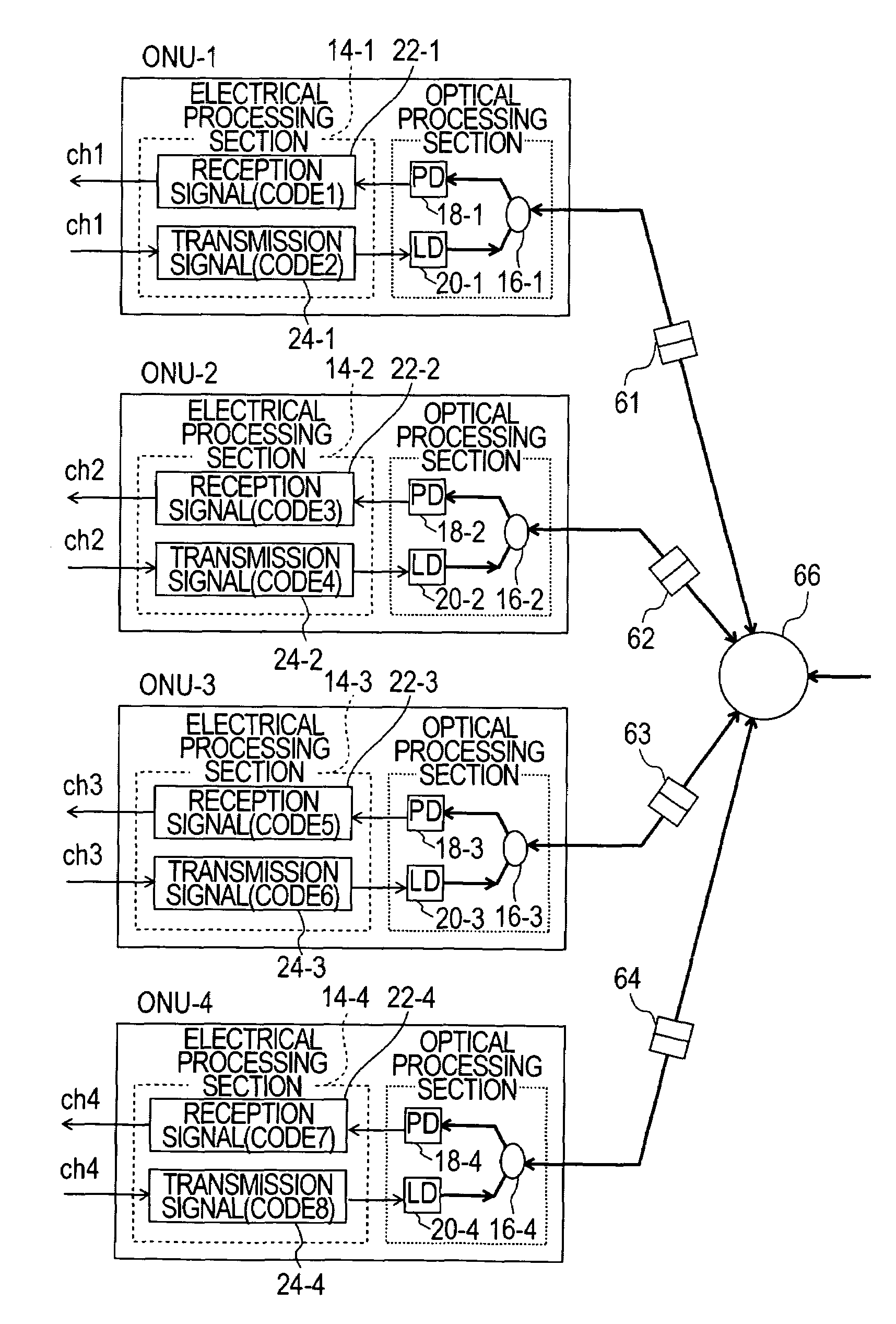
[0164]The optical access network system of the second invention is characterized in that code is selected so that the codes set for the transmitting signal processing section that the ONU comprises and the code that is set for the transmitting signal processing section that the OLT comprises differ from channel to channel. The constitution of the ONU in this case will now be described as Embodiment A with reference to FIG. 8. FIG. 8 is a schematic block constitutional view of the ONU of Embodiment A of the optical access network system of the second invention. FIG. 8 shows a view obtained by taking the constitution of the parts of the ONU of the optical access network system shown in FIG. 1, which is shown simplified to the extent required for the subsequent description.

[0165]The electrical processing section 14 shown in FIG. 1 corresponds to the electrical processing sections 14-1 to 14-4 shown in FIG. 8, the optical coupler 16 corresponds to the optical couplers 16-1 to 16-4 shown...

embodiment b

[0175]A selection method other than Embodiment A above which selects code so that the code that is set for the transmitting signal processing section that the ONU comprises and the code that is set for the transmitting signal processing section that the OLT comprises differ for each channel will now be described as Embodiment B with reference to FIG. 9. FIG. 9 is a schematic block constitutional view of the ONU of Embodiment B of the optical access network system of the second invention.

[0176]In this selection method, the code that is set for the transmitting signal processing section 24-1 that the ONU-1 of the first channel comprises is code 2 and the downlink signal from the OLT to the ONU-2 of the second channel is also encoded by means of code 2 and transmitted. The code that is set for the transmitting signal processing section 24-2 that the ONU-2 of the second channel comprises is code 3 and the downlink signal from the OLT to the ONU-3 of the third channel is also encoded by ...


PUM


Abstract

An optical access network system capable of transmitting and receiving high-speed signals and which allows the number of subscribers to be increased without increasing the number of wavelengths used is provided. An optical line terminal and an optical network unit are joined via an optical fiber transmitting line, a star coupler, and a plurality of branching optical fiber transmitting lines. The optical line terminal and optical network unit are constituted comprising an optical processing section and an electrical processing section. The optical processing section comprises a light-emitting element and a light-receiving element. The electrical processing section comprises a transmitting signal processing section that generates an encoded transmitting signal in the form of an electrical signal by encoding a transmitting signal and a receiving signal processing section that obtains a receiving signal by decoding a code-division-multiplexed signal that has been converted from optical-signal form to electrical-signal form by the light-receiving element. The optical access network system is characterized in that the decoding processing circuit that the receiving signal processing section comprises is constituted comprising an analog matched filter and a decision circuit.

Description

BACKGROUND OF THE INVENTION[0001]1. Field of the Invention[0002]The present invention relates to an optical access network system that allows a service provider and a subscriber to communicate by using a CDM (Code Division Multiplexing) system in a PON (Passive Optical Network).[0003]2. Description of Related Art[0004]An optical access network system constituted by connecting a service provider (also called the ‘center’ hereinbelow) and a plurality of subscribers (also called ‘users’ hereinbelow) via a PON has attracted attention. In the subsequent description, a service provider-side device is also called an optical line terminal or OLT and a subscriber-side device is also known as an optical network unit or ONU.[0005]A PON is a network that splits a single optical fiber transmitting line into a plurality of optical fiber transmitting lines by connecting a star coupler constituting a passive element midway along the optical fiber transmitting line and which connects a plurality of ...

Claims


Application Information

Patent Timeline
Patent Type & Authority Applications(United States)
IPC IPC(8): H04J14/00
CPCH04J14/02H04J14/005
Inventor KASHIMA, MASAYUKIIWAMURA, HEDEYUKI
Owner OKI ELECTRIC IND CO LTD
Learn More