
Integrated patch and assay device with visual detection means

a technology of visual detection and patch, applied in the field of assay devices, can solve the problems of patch leakage, back diffusion problems, excessive wear time, etc., and achieve the effect of rapid analyte detection process

Inactive Publication Date: 2007-08-02
PROVEX TECH
View PDF4 Cites 75 Cited by
  • Summary
  • Abstract
  • Description
  • Claims
  • Application Information

AI Technical Summary

Benefits of technology

[0004] What is needed are devices and methods capable of collecting a sample during a short interval combined with an rapid analyte detection process.
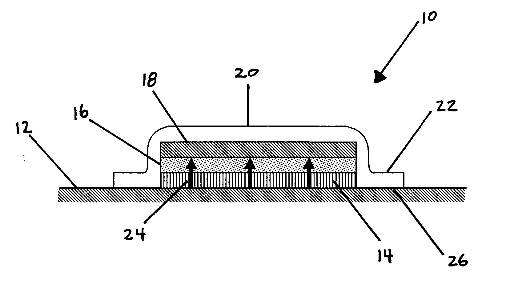
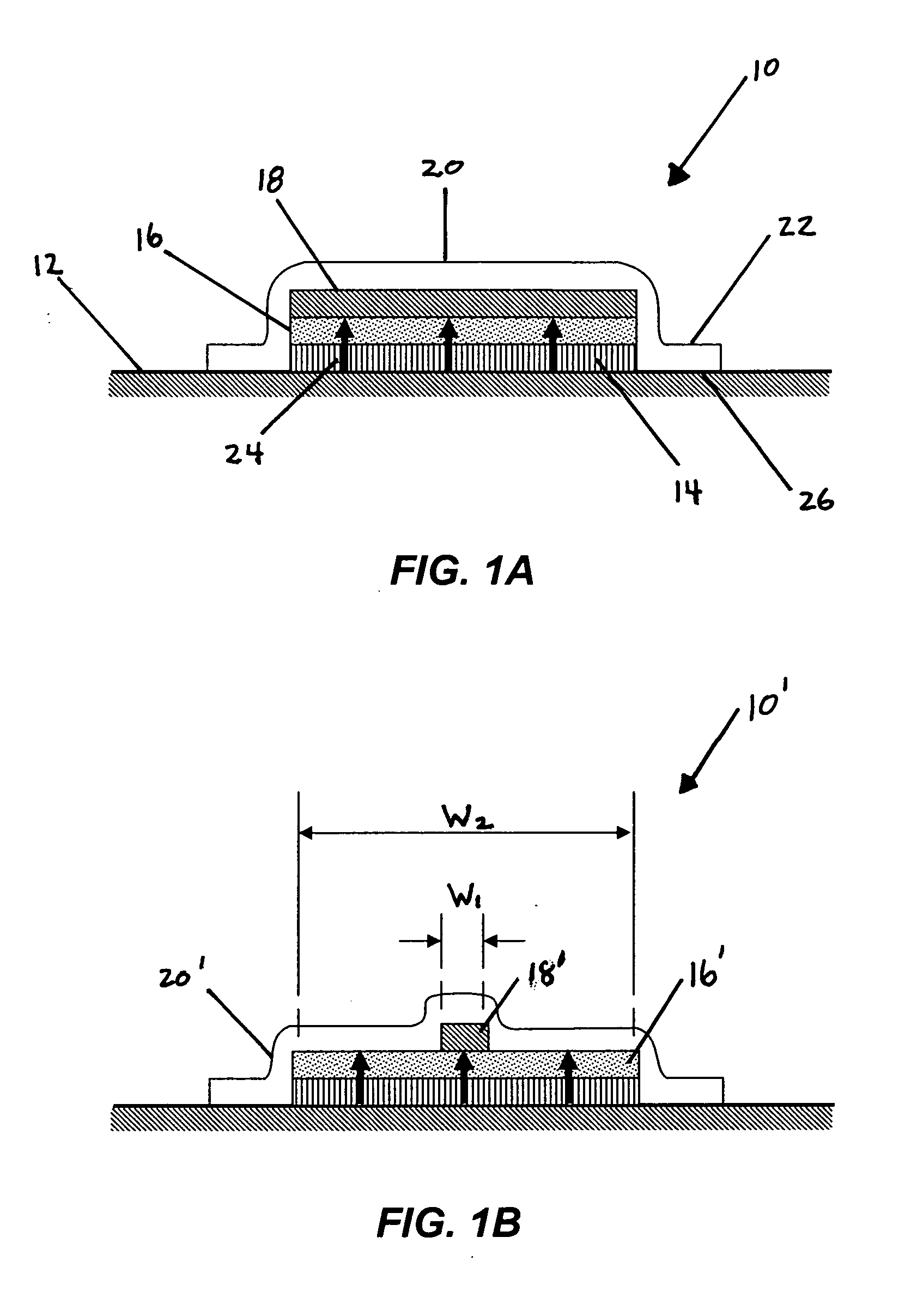
[0005] Various embodiments of the present invention can provide an integrated sample collection device incorporating an analyte detector, and a gradient means to actively and rapidly drive the transport of sample fluid from the point of contact to the point of detection and reading.

Problems solved by technology

Limitations associated with such technologies include excessively long wear times, patch leakage, back diffusion problems, lack of analyte binding to the pad layer to prevent resorption by the skin.
Other limitations include the need for normalization and correction of analyte concentration for actual sweat volume over time (over long term wear) through a supplemental procedure, such as the detection of potassium values by flame photometry in a laboratory.
Accordingly, such devices are not well suited for applications in which a rapid sample and analyte detection process is necessary.

Method used


Image

  • Integrated patch and assay device with visual detection means
  • Integrated patch and assay device with visual detection means
  • Integrated patch and assay device with visual detection means

Examples


example 1

[0060] Referring to FIG. 3A and FIG. 3B, a multilayered laminate 50 of acrylic, non-sensitizing, medical grade skin adhesive 50, are adhered to clear 2.0 mil thick occlusive layer 53 and 60# siliconized Kraft release liner paper 54. Each of the layers can be dye cut into a preferred size and shape, such as 2.5 cm diameter circles 56. A smaller, 1.5 cm circle of release line is removed from the center of the triple-layered laminate (not shown) exposing the underlying adhesive and leaving a 0.5 cm width peripheral ring of release paper intact 54. Suitable skin adhesives include HY-3 High MVTR, commercially available from Adhesives Research, Inc., Glen Rock, Pa. The occlusive layer 53 can be formed from polyethylene terephthalate (PET), commercially available from Polyester Converters, of Fullerton, Calif.

[0061] A method described in Trinder, P., Ann. Clin. Biochem. 6 (1969) 24, can be modified for colorimetric detection of glucose. Sheets of 0.45 micron polyester reinforced polysulfo...

example 2

[0065] Referring to FIG. 4A and FIG. 4B, a laminate of acrylic medical grade adhesive HY-3 High MVTR (commercially available form Adhesives Research, Inc., of Glen Rock, Pa.) is adhered to clear 2.0-mil thick polyethylene terephthalate (PET) (commercially available Polyester Converters, of Fullerton, Calif.) (shown herein as 70 and 60# siliconized Kraft release liner paper (not shown) can be cut into a 1.0 cm wide×7 cm long strip. A 1.0 mm wide×6.5 cm long×0.25 mm deep channel 72 can be thermoformed into the trilayer laminate by pressing the laminate into a heated aluminum mold containing a raised aluminum line of comparable size on one side and a corresponding depression of comparable size on the other. The release liner side of the laminate can be placed toward the raised side in order to create a microchannel 72 in the laminate surface raised away from the point of application.

[0066] Next a 0.15 mm air pinhole 74 is made in the laminate channel 72 at the top end, at the 6.0 cm p...


PUM

PropertyMeasurementUnit
pore diameteraaaaaaaaaa
pore sizeaaaaaaaaaa
pore sizeaaaaaaaaaa

Abstract

Methods and apparatus for collecting a fluid sample using an integrated collection device are disclosed. The integrated collection device includes an analyte detector and a gradient means to actively and rapidly drive the transport of a sample fluid from the point of contact to the point of detection and reading. The analyte detector can include a visually-read colorimetric detector using a chemical or enzymatic detection process. The gradient means can include physical and / or chemical processes as described in more detail herein. In some embodiments, the device is provided as an occlusive patch. Preferably, the test device provides a reading immediately upon fluid contact with the analyte detector. Consequently, the time-to-result is sample volume and transport time dependent. By providing immediate or nearly immediate reading of results, the device is particularly useful in those applications in which immediate results are advantageous.

Description

CROSS-REFERENCE TO RELATED PATENT APPLICATIONS [0001] This application claims priority from U.S. Provisional Application Ser. No. 60 / 753,213, filed on Dec. 22, 2005, incorporated herein by reference in its entirety.FIELD OF THE INVENTION [0002] The present invention relates generally to assay devices and more particularly to assay devices combined with a fluid sampling capability. BACKGROUND OF THE INVENTION [0003] The use of non-occlusive patch technology for the analysis of alcohol and drugs of abuse is under development. Limitations associated with such technologies include excessively long wear times, patch leakage, back diffusion problems, lack of analyte binding to the pad layer to prevent resorption by the skin. Other limitations include the need for normalization and correction of analyte concentration for actual sweat volume over time (over long term wear) through a supplemental procedure, such as the detection of potassium values by flame photometry in a laboratory. Accord...

Claims


Application Information

Patent Timeline
Patent Type & Authority Applications(United States)
IPC IPC(8): A61B5/00G01N21/00G01N31/22
CPCA61B5/1486A61B5/6833A61B2560/0412B01L3/5023B01L2300/0681G01N31/22B01L2400/0406B01L2400/084G01N21/01G01N21/78B01L2300/0887
Inventor PRONOVOST, ALLAN D.
Owner PROVEX TECH
Learn More