Tire pressure sensor system with improved power saving

a technology of tire pressure sensor and power saving, which is applied in vehicle tyre testing, instruments, roads, etc., can solve the problems of limited performance of such devices, limited sensitivity of sensor circuit to single strain gauge variable resistance range, and relatively insensitive sensors to mechanical vibration. , to achieve the effect of enhancing measurement sensitivity, reducing power consumption, and low cos

Inactive Publication Date: 2007-08-09
SILICON VALLEY MICRO C CORPORATION
View PDF4 Cites 0 Cited by
  • Summary
  • Abstract
  • Description
  • Claims
  • Application Information

AI Technical Summary

Benefits of technology

[0007] The invention comprises a method and system for monitoring internal vehicle tire pressure employing a power saving unit providing extended useful battery life.
[0009] The power saving unit has an input terminal adapted to be coupled to a source of electrical power (the battery in a particular embodiment), an output terminal for supplying electrical power to the sensor, and a vehicle speed sensitive switch for connecting the input terminal to the output terminal when the tire attains a first predetermined speed and for disconnecting the input terminal from the output terminal when the speed of the tire drops below the first predetermined speed. In one embodiment, the switch comprises an electrically conductive contact member, such as a spring, having a first portion connected to the output terminal and a free end, and an electrically conductive pivot member, such as a spring or a pivot arm, having a first portion connected to the input terminal and a mass member mounted on a free end. The mass member is mounted to make physical contact with the free end of the contact member when the tire attains the first predetermined speed, thus enabling the transfer of electrical power from the input terminal to the output terminal. Preferably, the mass member has opposing ends; and the switch is provided with first and second contact members connected to the output terminal, with the first contact member having a free end located in the path of one of the opposing ends of the mass member, and the -second contact member having a free end located in the path of the other one of the opposing ends of the mass member. With this configuration, the positioning of the power saving unit on a vehicle tire is facilitated.
[0017] The invention provides a convenient solution to the problem of monitoring internal tire pressure in vehicles equipped with pneumatic tires. The system can be installed either during manufacture of a new tire, manufacture of a new vehicle or as an aftermarket item. Further, existing vehicles without tire pressure sensor systems can easily be retrofitted with a state-of-the-art system at relatively low cost. This is particularly beneficial in jurisdictions which mandate low tire pressure warning devices on all road vehicles. The sensor assembly provides substantially enhanced measurement sensitivity, and the power saving unit substantially reduces power consumption, which is particularly important in those installations which use a relatively inaccessible battery as a source of electrical power.

Problems solved by technology

This type of sensor is relatively insensitive to mechanical vibrations, which are regularly encountered in an automotive environment.
In spite of the effectiveness of the known sensor circuitry using the strain sensor and bridge circuit, there are inherent limitations which limit the performance of such devices.
Firstly, due to the fact that only a single variable resistance element (the strain gauge) is incorporated into one branch of the bridge circuit, the sensitivity of the sensor circuit is limited to the variable resistance range of the single strain gauge used.
This limits the potential measurement range of the sensor system.
In addition, the known sensor circuitry is susceptible to measurement inaccuracies due to different coefficients of thermal resistivity of the variable resistance strain sensor and the fixed resistances forming the bridge circuit.
Secondly, since the sensor circuitry is continuously powered by the essential battery, the useful lifetime of the battery is limited by the battery energy capacity.
This drawback is compounded by the need for components having relatively small physical size due to installation constraints.
As a consequence, battery replacement is a major constraint to the efficacy of such known sensor systems.
Efforts to provide a simple yet accurate and durable tire pressure monitoring system devoid of the above-noted disadvantages have not been successful to date.

Method used


Image

  • Tire pressure sensor system with improved power saving
  • Tire pressure sensor system with improved power saving
  • Tire pressure sensor system with improved power saving

Examples


Embodiment Construction

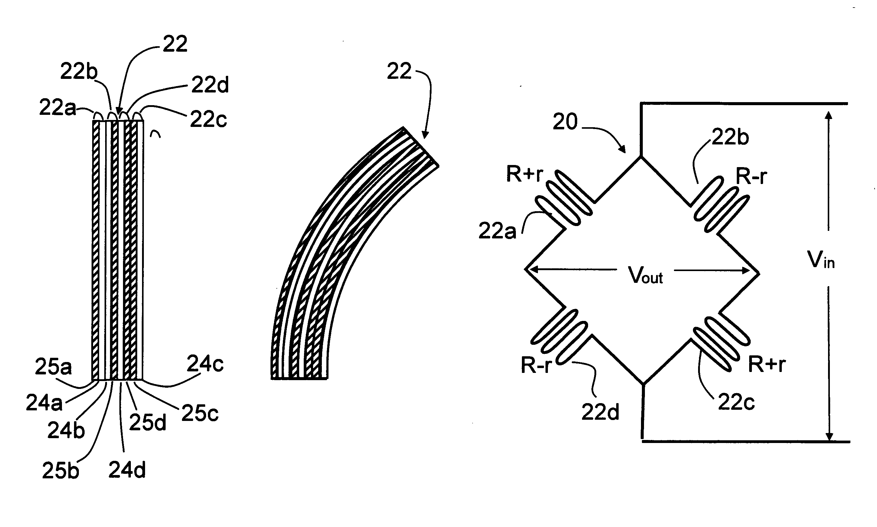
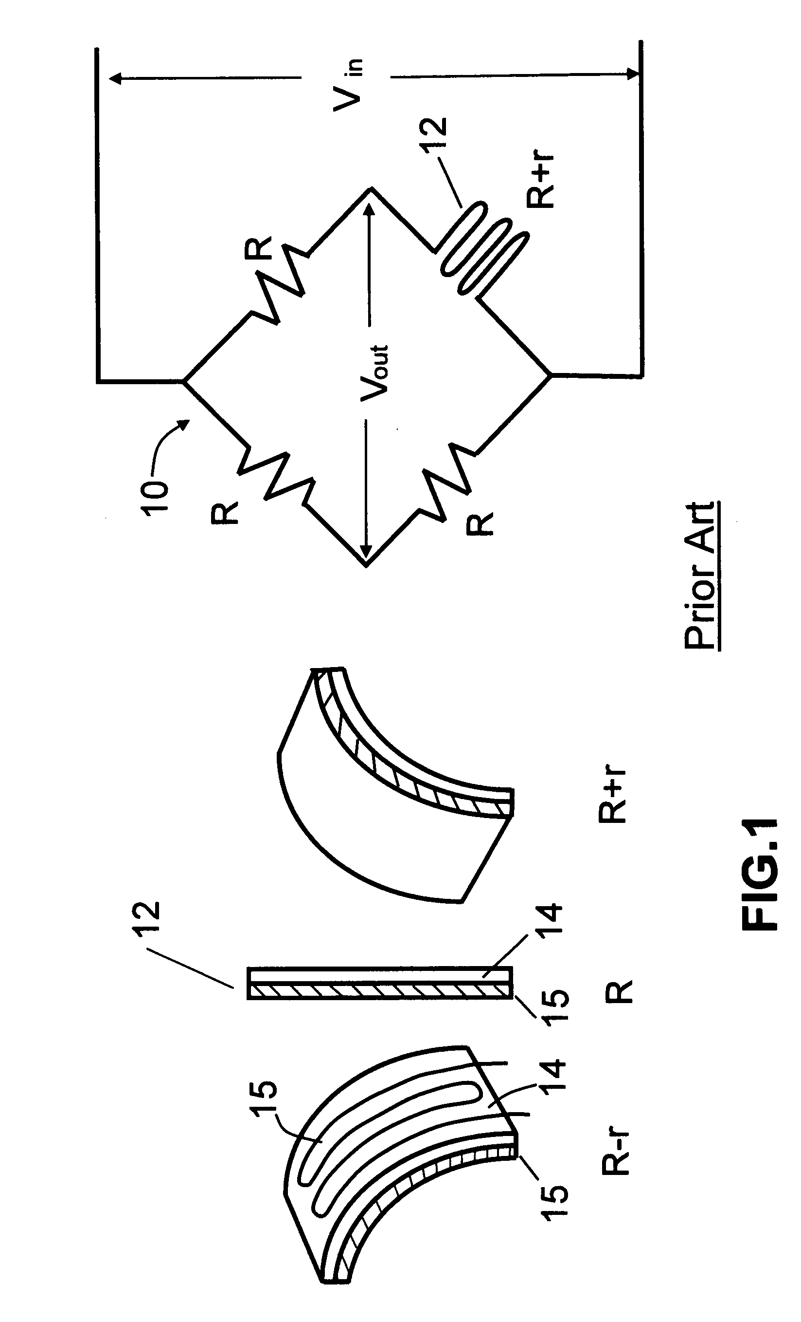
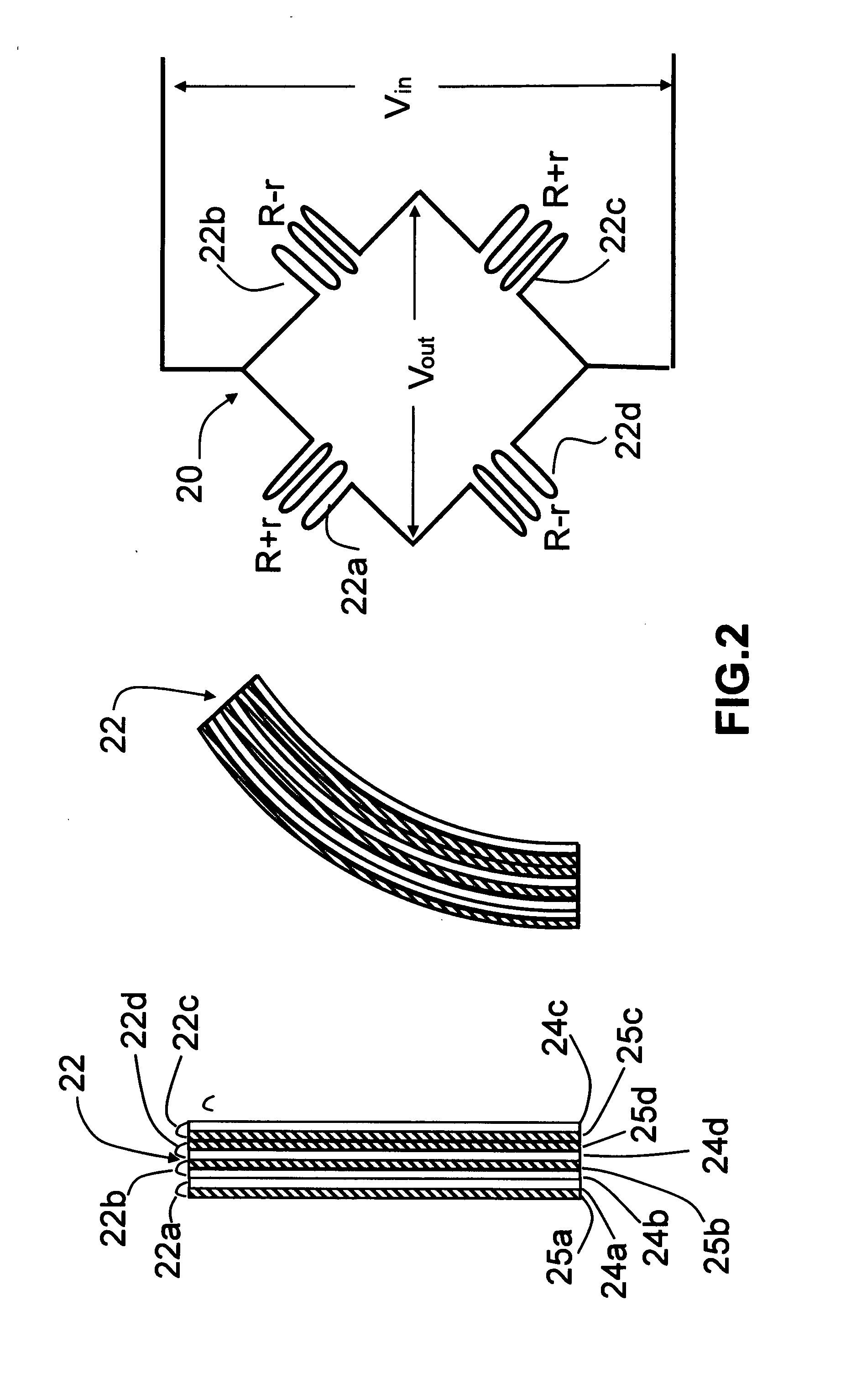
[0032] Turning now to the drawings, FIG. 1 is a schematic view of a prior art single tire pressure monitor circuit using a single stretch sensor in a bridge circuit. As seen in this Fig., the monitor circuit, generally designated with reference numeral 10, includes a single stretch sensor 12 ohmically connected in one branch of a bridge circuit having three additional branches each with a fixed resistance R ohmically connected as shown. Stretch sensor 12 is a known component having the property of an ohmic resistance which varies in a predictable amount with linear longitudinal displacement of the sensor body. Stretch sensor 12 has a first layer 14 on which a thin variable resistance element 15 is mounted; and a second, base layer which carries the first layer and provides additional mechanical strength for sensor 12. The fixed resistances R are all of equal value. A reference voltage Vin from a source of D.C. electrical power (not shown) is applied to two nodes of bridge circuit 10...


PUM


Abstract

A battery powered vehicle tire pressure sensor system has a power saving unit which controls the application of electrical power to the system as a function of tire speed to prolong battery life. The power saving unit has a power control switch which is responsive to tire angular speed. Each sensor assembly of the system is mounted on or in the side wall of a pneumatic tire to generate signals representative of tire pressure whenever power is applied. A processor periodically samples the signals. When the processor determines that the tire pressure is outside a safe range, an r.f. generator is activated by the processor to generate an unsafe tire pressure signal. This signal is converted by a receiver to a warning for the driver.

Description

CROSS-REFERENCE TO RELATED APPLICATION [0001] This application is a divisional application of U.S. patent application Ser. No. 11 / 267,775 filed Nov. 4, 2005 for “Tire Pressure Sensor System With Improved Sensitivity And Power Saving”.BACKGROUND OF THE INVENTION [0002] This invention relates to automotive tire pressure sensors. More particularly, this invention relates to a battery powered method and system for monitoring internal tire pressure of vehicle tires using a sensor system with improved sensitivity and a power saving device. [0003] Tire pressure sensor systems are known and are commonly used to monitor the internal air pressure in individual pneumatic tires of a vehicle and to provide a warning signal to the driver whenever the internal air pressure in one or more of the vehicle tires is dangerously low or high. The warning signal is typically generated by an r.f. signal generator controlled by a microprocessor connected to the tire pressure sensor, the warning signal being...

Claims


Application Information

Patent Timeline
Patent Type & Authority Applications(United States)
IPC IPC(8): G01M17/02
CPCB60C23/06
Inventor HUANG, SU SHIONGZHU, SHENGBO
Owner SILICON VALLEY MICRO C CORPORATION
Why Eureka
Try Eureka