Rtm molding method and device

a technology of resin transfer molding and molding method, which is applied in the direction of manufacturing tools, food shaping, drawing profiling tools, etc., to achieve the effects of reducing production costs, shortening molding time, and increasing production speed and production amoun

Inactive Publication Date: 2007-08-09
TORAY IND INC
View PDF14 Cites 79 Cited by
  • Summary
  • Abstract
  • Description
  • Claims
  • Application Information

AI Technical Summary

Benefits of technology

[0066] In the RTM molding method and device according to the present invention, since adequate divided areas are assumed and the injected resin can be delivered enough to the respective divided areas and can be impregnated well into the respective divided areas even if a reinforcing fiber substrate with a relatively large area is used, the molding process from resin injection to impregnation and curing can be carried out at a high speed without generating non-resin-flowing areas, thereby achieving shortening of the molding time and increase of production speed and production amount, and reducing the production cost. Further, the resin can be impregnated at a desirable state over the entire are a, thereby improving the surface quality of the molded product.
[0067] In particular, in the RTM molding method and device according to the first embodiment, since the resin is flown in advance so as to be spread to a sufficiently wide area via the intermediate member and thereafter the resin is injected into the reinforcing fiber substrate from a plurality of positions almost simultaneously and uniformly, even as for a relatively large three-dimensional configuration, the molding can be carried out at a high speed without generating non-resin-flowing areas. As a result, the molding time is greatly shortened, it becomes possible to increase the production speed and the production amount, and it becomes possible to reduce the production cost by increasing the production amount per one mold. Further, Even as for a large-sized product to be molded, it becomes possible to easily prevent generation of resin non-impregnated portions, thereby improving the quality of the molded product.
[0068] Further, in the RTM molding method and device according to the second embodiment, a relatively large FRP product can be molded efficiently and stably in a short period of time without occurrence of defects such as voids, which has been difficult by a conventional RTM molding method. Namely, mass production with a high-cycle becomes possible.
[0069] Furthermore, in the RTM molding method according to the third embodiment, by disposing the random mat layer with a weight lower than that of the layer of surface layer or the layer of the reinforcing fiber substrate immediately under the continuous fiber substrate of at least one surface layer, when the resin is injected and impregnated into the reinforcing fiber substrate, resin flow paths with a small flow resistance and easy to flow resin are formed, and the injected resin is well delivered up to the detailed portions because the fiber orientation is random, thereby preventing occurrence of defects such as voids and pinholes ascribed to resin non-impregnated portions. In particular, by a condition where the random mat layer is disposed immediately under the surface layer, it can be efficiently prevented that such defects are generated on the surface of the molded product, and the surface quality of the molded product, particularly, the quality of the design surface, can be effectively improved.
[0070] [FIG. 1]FIG. 1 is an exploded perspective view of a device used in an RTM molding method according to a first embodiment of the present invention.
[0071] [FIG. 2]FIG. 2A is a plan view of an upper die of the device depicted in FIG. 1, and FIG. 2B is an elevational view thereof.

Problems solved by technology

In such a conventional method, however, there is a problem that RTM molding of a large product is difficult, because it is difficult to set a large amount of flowing resin and there is only one resin injection port.
Further, if the time of gelation is extended by adding a delay agent to the resin, it is possible to flow the resin over the entire area although a long time is required, but too much time is required for achieving a predetermined resin flow, thereby decreasing the production speed and the production amount.
Even if the resin flow is controlled by providing a plurality of resin discharge ports, there is a limit for molding a complicated structure properly.
In this method, non-impregnated reinforcing fiber substrate applied with a semi-cured resin film is heated, and molten resin is impregnated by pressing it by hot press and the like, but a complicated-shape molding is difficult, and there is a problem that a non-impregnated portion is liable to occur in a part of the reinforcing fiber substrate.
Since any of these methods is not a method for impregnating a matrix resin into a reinforcing fiber substrate while flowing the molten resin from initial time, there left a cause for generating non-impregnated portions.
In such a method, however, although the resin surely flows from one side toward the opposite side while the resin is impregnated into a reinforcing fiber substrate in order, if the product to be molded is relatively large, it takes much time to flow the resin, and as the case may be, the resin may reach a time of its gelation during its flow, in such a condition there is a problem that the resin flow stops before complete impregnation.
In this method, however, since the resin is injected from portions within a molding area of the product to be molded, it cannot be applied to a sandwich molded product using a core material and disposing reinforcing fiber substrates on both surfaces of the core material, because the resin cannot be injected from a mold surface side.
Further, even in a case of a non-sandwich molded product, the method cannot be applied to the molding of a product which is double-sided and which requires a high design quality for its surface.
Thus, in the above-described conventional RTM molding methods, it is difficult to efficiently mold a relatively large product.
Usually, in an RTM mold consisting of relatively many dies, there is a big problem that the productivity is low, because the molding takes much time.
In particular, in a case where resin injection is carried out at a high resin discharge pressure of 0.5 MPa or more (therefore, at a high flow rate) in order to shorten a molding time or in order to mold a product having a large area in a short period of time, disturbance of the weave structure of a reinforcing fiber substrate (particularly, a plain weave fabric) is liable to occur, and further, because the resin flows in the mold at a high speed, the resistance against the flow disperses within the flow area depending upon a dimensional unevenness (particularly, an unevenness in thickness) of a cavity in the mold, a fine unevenness in thickness of the substrate, or a difference between partial structures of the substrate due to overlapping of substrate layers and the like, and because a uniform flow cannot be maintained, there is a case where a large void is generated by occurrence of a local forestalling of the resin flow and the like.
Furthermore, there is a case where the resin actually flows up to the substrate portion, but, because the flow rate is high, for example, there is no time for release of gas present in the texture of the woven fabric and the gas stays there, and the gas generates a surface defect such as a pinhole.
In such conventional molding conditions and molding process causing reduction of quality in appearance concerning the design quality such as substrate disturbance, voids and pinholes, it is difficult to ensure a high surface quality while carrying out a high-speed injection for shortening the molding time.
The larger the size of a product to be molded becomes, the more frequently such defects on quality in appearance are liable to occur, because a high-speed resin injection is to be inevitably employed.
Namely, if the weight is too great and the rigidity of the substrate becomes high, the reinforcing fiber substrate becomes hard to be situated along the mold surface and hard to be formed in a three-dimensional shape, and there is a case where it takes much working time to make a preform, or that at that time disturbance of the substrate occurs and the mechanical properties of the FRP molded product decrease.
If a temperature of injected resin itself or a resin temperature heated by a mold is high, the resin viscosity reduces and the flowability of the resin increases, and although the impregnation property of the resin into the substrate is good, the flowability rapidly deteriorates by a high elevation rate of the viscosity, and when the molded product is big, there is a case where the flow of the resin reduces in speed on the way of the molding and it causes a non-impregnated portion.
On the other hand, if there is an unevenness of the temperature of a mold or there is a change in the temperature during molding, there is a case where very fine gas bubbles remaining in the mold come into contact with each other and they grow a big bubble developing to a void or a pinhole.
Namely, if the pressure is too high, the resin flow rate becomes high, and there is a case where it causes a disturbance of the weave structure of the substrate or it causes an expansion in volume in a cavity to generate bubbles, and if the pressure is too low, there is a case where residual bubbles cannot be compressed to be small.
Therefore, the reaction speed reduces, and there is a case where the time required for the curing becomes long.
Thus, in FRP molding (particularly, RTM molding), there exist proper molding conditions and material characteristic in accordance with molding size (area), and if not molded at proper conditions, problems on quality, in particular, on surface quality, are liable to occur.
In such a conventional molding method, however, if a resin to be injected and cured is not delivered enough and is not impregnated into the details of the reinforcing fiber substrate, voids and pinholes may occur, and the mechanical properties of the molded product may be decreased, or the surface quality may be reduced.
Especially, if voids or pinholes appear on the surface, in particular, on the design surface side, although usually patching such as charge of resin is carried out, this patching requires work and time, and decreases the efficiency of the whole of the manufacturing process.
In a case where such a substrate structure is employed in a molding method such as RTM molding and vacuum molding wherein a resin fluid is injected into a dry substrate and flown and impregnated into the substrate, it is necessary to discharge also bubbles by the flow of the resin, and at a portion with a low resin flowability, voids are liable to be generated or pinholes are liable to occur by the left bubbles.
Therefore, the resin flowability into the gap is poor, and as a result, voids and pinholes are liable to occur at the position thereof.
Thus, particularly in an RTM molding method and a vacuum molding method, even if a random mat layer is provided as an outermost layer (a surface layer at a design surface), occurrence of voids and pinholes cannot be prevented.

Method used


Image

  • Rtm molding method and device
  • Rtm molding method and device
  • Rtm molding method and device

Examples


example 1

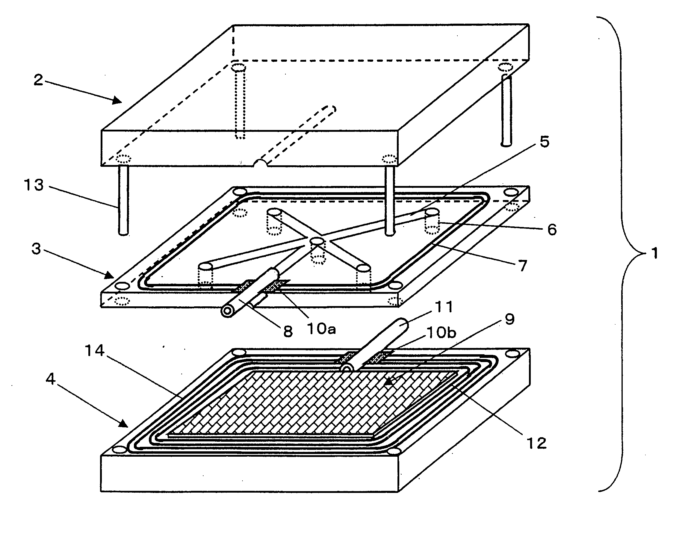
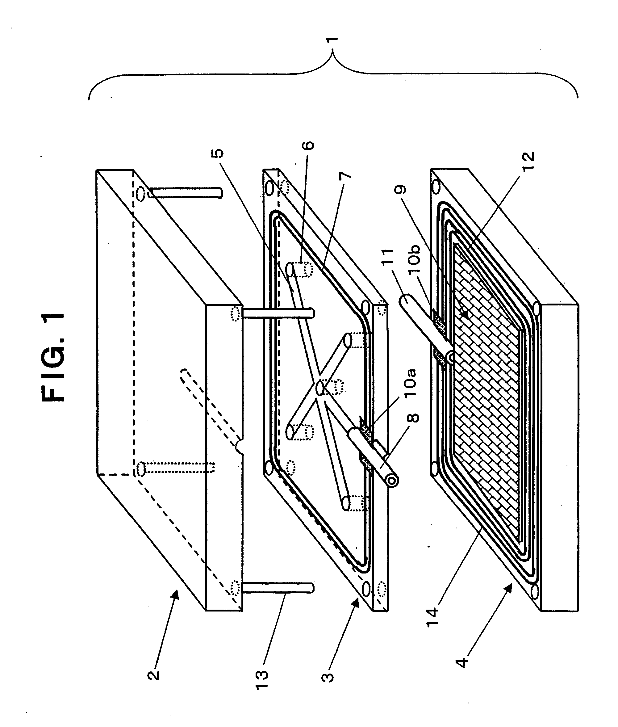
[0191] In the above-described respective embodiments, when molding was carried out setting the size of a mold at 1500 mm×1200 mm×depth 3 mm at the molding surface (the cavity surface), using a laminate of 8 plies of “TORAYCA” T700 cloth BT70-30 (300 g / m2) produced by Toray Industries, Inc. as the reinforcing fiber substrate, and using a high-speed curing type epoxy resin (main ingredient: “Epicoat”828 (an epoxy resin produced by Yuka Shell Epoxy Corporation), curing agent: blend TR-C35H (an imidazole derivative) produced by Toray Industries, Inc.) as the resin, in spite of a relatively large molded product, a good and quick molding could be carried out. Where, the time for completing the impregnation of the resin into the substrate was 5 minutes or less at a resin injection pressure of 0.7 MPa, and could be shortened down to ⅕- 1 / 10 or less of a conventional method.

[0192] FIGS. 8 to 12 show RTM molding method and device according to the second embodiment of the present invention. F...

example 2

[0212] In the RTM molding system 54 according to this embodiment shown in FIG. 11, as an example of molding at molding conditions according to the present invention, an example of molding of a large flat plate (length of 1600 mm×width of 700 mm×height (thickness) of 2 mm) will be explained. The whole of the RTM mold 41 used in this example is shown in FIGS. 8 and 9, and the relationship between the temperature and the viscosity of the resin used for the molding and the property in resin curing degree-time at the molding temperature are shown in FIG. 12A and FIG. 12B, respectively. On the molding cavity portion 50 provided on the lower die 43 of the mold 41 (length: 2000 mm, width: 1000 mm and height: 350 mm in each of upper die 42 and lower die 43) having resin injection tubes 46 to 48 and discharge tube 49, carbon fiber “TORAYCA” cloth (CO6343B: T300B-3K, weight: 192 g / m2) is laminated by 8 plies (0 / 90° oriented substrates: 4 plies, ±45° oriented substrates: 4 plies), a preform sub...

example 3

[0226] Although the above-described Example 2 employed a single plate structure of reinforcing fiber substrate, as another example, when employed was a carbon fiber reinforcing structural material including a foam core (thickness: 10 mm, apparent specific gravity: 0.1) therein (three plies of the above-described carbon fiber “TORAYCA” cloths were stacked on each of the upper and lower surfaces of the foam core), an almost similar molded product excellent in surface quality could be obtained. Where, the time for impregnation was about 4.5 minutes, and was a short period of time similarly to the above-described example.

[0227] Next, an RTM molding method according to a third embodiment of the present invention will be explained. First, the production of the fiber reinforced resin molded by this RTM molding method will be explained referring to FIG. 18. As shown in FIG. 18A, a resin injection port 85 and a suction port 86 are provided on an upper die 83 of the double-sided mold. Lower ...


PUM

PropertyMeasurementUnit
temperatureaaaaaaaaaa
pressureaaaaaaaaaa
pressureaaaaaaaaaa

Abstract

An RTM molding method comprising disposing a reinforcing fiber substrate in a cavity of a mold consisting of a plurality of dies, clamping the mold, and thereafter injecting resin to complete molding, characterized in that divided areas with respect to the surface direction of the reinforcing fiber substrate are assumed, each divided area is one in which injected resin expands over the entire surface in the area and can be substantially uniformly impregnated in the thickness direction of the substrate, and resin introducing paths are formed for respective assumed divided areas for introducing the injected resin into the respective divided areas; and an RTM molding device. When a relatively large molded product is to be molded, a molding step from resin injection to impregnating/curing can be implemented at high speed without generating a non-resin-flowing area, thereby enabling a high-quality molded product to be produced free from voids, etc., with a molding time shortened and production speed and volume increased.

Description

TECHNICAL FIELD OF THE INVENTION [0001] The present invention relates to RTM (Resin transfer Molding) molding method and device for molding a relatively large FRP (Fiber Reinforced Plastic), and more specifically, to RTM molding method and device capable of achieving a high-speed molding and improving a surface quality. BACKGROUND ART OF THE INVENTION [0002] FRP, in particular, CFRP (carbon fiber reinforced plastic), is utilized in various fields as a composite material having a property light in weight and high mechanical properties. As one of FRP molding methods, an RTM molding method is known wherein a reinforcing fiber substrate such as a laminated substrate of reinforcing fiber woven fabrics is placed in a mold, and after the mold is clamped, a liquid resin is injected into the mold reduced in pressure, and the resin is heated and cured. Further, in such a conventional molding, it is proposed to give a certain shape to a reinforcing fiber substrate before disposing it in a mold...

Claims


Application Information

Patent Timeline
Patent Type & Authority Applications(United States)
IPC IPC(8): B29C70/48B29C33/00B29C39/10B29C39/24B29C39/42B29C70/54
CPCB29C33/0066B29C70/48B29C33/10B29C70/081B29C70/548B29C39/10B29C39/24B29C39/42
Inventor SEKIDO, TOSHIHIDEIWASAWA, SHIGEOSENBA, TATSUYA
Owner TORAY IND INC
Why Eureka
Try Eureka