LCD backlight driver

a backlight driver and driver technology, applied in the field of liquid crystal displays, can solve the problems of influencing events that affect sudden starts for a lifetime, and achieve the effect of improving any visual artifacts and excellent control of driving waveforms

Inactive Publication Date: 2007-08-09
TEXAS INSTR INC
View PDF4 Cites 24 Cited by
  • Summary
  • Abstract
  • Description
  • Claims
  • Application Information

AI Technical Summary

Benefits of technology

[0004] This disclosure provides methods and apparatus for excellent control over the driving waveform. Additionally, the disclosed methods and apparatus can be used to stagger the phase of the multiple bulb

Problems solved by technology

The bulbs are typically driven with a sinusoidal waveform; howe

Method used


Image

  • LCD backlight driver
  • LCD backlight driver
  • LCD backlight driver

Examples


Embodiment Construction

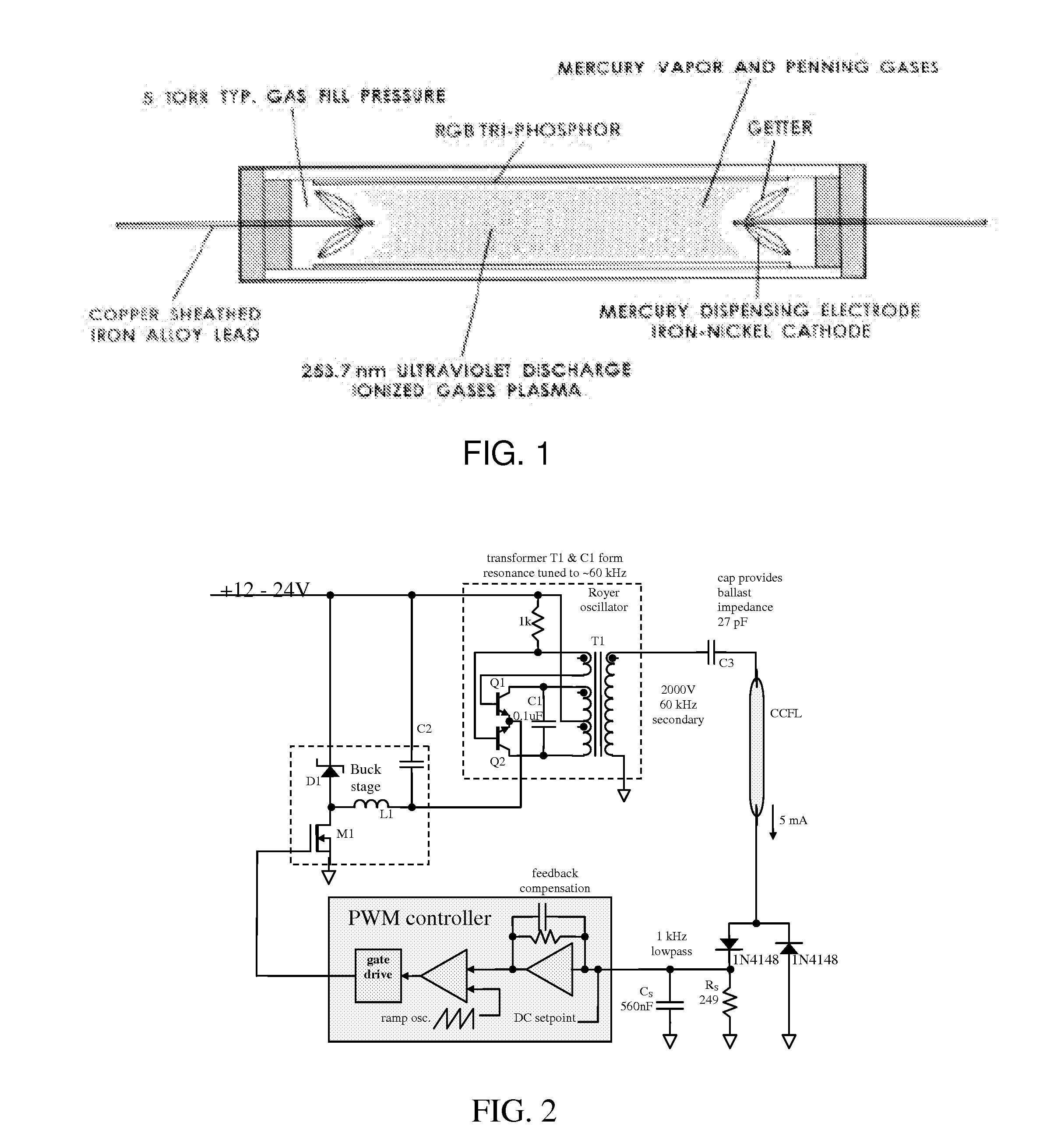
[0024] Cold Cathode Fluorescent Lamps (CCFL) and External Electrode Fluorescent Lamps (EEFL) are similar to the neon gas-discharge lamp invented in 1910 by Georges Claude in Paris, France. Like all fluorescent lamps, they work by applying a sufficiently large voltage across the device to ionize the contained gas which stimulates the phosphor coating inside the glass lamp envelope.

[0025] CCFLs are so named because of the type of electrode in the lamp ends. Unlike architectural fluorescent lamps, cold cathode electrodes do not rely on additional means of thermonic emission besides that created by the electrical discharge The typical CCFL is a hollow glass cylinder coated inside with a phosphor material composed of rare earth elements and sealed with a gettered electrode at both ends. The lamps normally contain 2-10 milligrams of mercury along with a mixture of gases, such as argon and neon. Ultraviolet energy at 253.7 nm is produced by ionization of the mercury and penning gas mixtur...


PUM


Abstract

Three example inverter designs are described that can be tailored to drive from one to dozens of lamps of a backlight for a liquid crystal display. For each design the lamps are driven by a 40 kHz to 60 kHz sine wave. The lamp voltage is ˜1200V to “strike” the lamps and ˜600V to produce the optimal 5 mA in each lamp. The designs are: a Royer linear oscillator driven by a buck converter stage, a push-pull inverter that drives the high voltage transformer directly, and a class-D amplifier that produces the drive sine wave using a pulse width modulation technique.

Description

CROSS-REFERENCE TO RELATED APPLICATIONS [0001] This application claims priority of U.S. Provisional Application Ser. No. 60 / 704,612, filed Aug. 2, 2005.TECHNICAL FIELD [0002] The invention relates to Liquid Crystal Displays (LCDs) and, more particularly, to improved drivers for digitally controlling a CCFL / EEFL backlight inverter for an LCD. BACKGROUND [0003] LCDs (Liquid Crystal Displays) require a backlight which consists of several fluorescent tubes. The lifetime of these tubes is one of the major factors influencing reliability of the display. While all the factors that influence lifetime are not completely understood, one of the factors is the waveform of the voltage driving the bulbs. The bulbs are typically driven with a sinusoidal waveform; however, sudden starts are known to be a lifetime influencing event. With the uncertainty of factors affecting life, more control of the waveform is desirable. SUMMARY OF THE INVENTION [0004] This disclosure provides methods and apparatus...

Claims


Application Information

Patent Timeline
IPC IPC(8): H05B41/16
CPCH05B41/2858
Inventor HAGEN, MARK DAVIDOETTINGER, ERIC GREGORY
Owner TEXAS INSTR INC
Why Eureka
Try Eureka