
Mold for in-mold decoration

a technology of in-mold decoration and molds, which is applied in the field of molds for in-mold decoration, can solve the problems of increasing the wasteful use of decorating films, increasing the manufacturing cost of molds, and the inability to meet the short delivery period required in mold manufacturing, so as to reduce the need for recessing, shorten the time necessary for mold manufacturing, and reduce the effect of production cos

Inactive Publication Date: 2007-08-09
NISSHA PRINTING COMPANY
View PDF5 Cites 31 Cited by
  • Summary
  • Abstract
  • Description
  • Claims
  • Application Information

AI Technical Summary

Benefits of technology

[0027] According to the present invention, instead of attaching the pockets into which the cavity-forming blocks are fitted to the dieset, the dieset and the cavity-forming block are positioned and joined by the engagement protruding portion provided either one of the dieset and the cavity-forming block and the engagement recess portion provided on the other, and further a plurality of clamping force-receiving portions are disposed partly around the cavity-forming block instead of forming a frame shape, so that a clearance where the force-receiving portions are not provided can be used to smooth the mounting face, which eliminates the necessity of recessing and facilitates smoothing of the mounting face. This makes it possible to shorten time necessary for mold manufacturing, thereby allowing low price and short delivery period to be realized, while contributing to sable mass-production in molding process. Moreover, if the mounting face is structured to be on the same plane as the smoothing face, the smoothing face makes the edges of the face subject to smoothing open, which allows the mounting face and the smoothing face to be collectively processed, and thereby allows smoothing to be further facilitated.
[0028] Moreover, since the cavity-forming block is provided on the passing region of the decorating film, and the clamping force-receiving portions are provided outside the passing region of the decorating film and the mounting face, the clamping force will not be exerted on the decorating film when both the bolds are closed. This prevents the film from being damaged during in-mold decoration process. Further, the cavity-forming block is mounted on the dieset not by the pocket but by the engagement protruding portions and the engagement recess portions, which makes it possible to smooth the mounting face of the dieset and dispose the cavity-forming blocks in parallel with each other. Therefore, such problem as occurrence of fins in resulting molded articles can be prevented and gases present in the cavity and the like can be discharged smoothly.
[0029] Further, the clamping force-receiving portions are present outside of the cavity-forming block and it is not necessary to form them into a frame shape, or more preferably, a clearance is provided between the clamping force-receiving portions and the cavity-forming block, so that contact portions between the clamping force-receiving portions and the cavity-forming block can be decreased, making it possible to reduce the amount of heat conducted from the cavity-forming block to other members. This facilitates temperature control including temperature control of the molds.

Problems solved by technology

For preventing such problems, it would become necessary to take sufficient time in order to machine the pockets 62 with high precision, but this would make it impossible to meet short delivery periods required in mold manufacture.
Also, taking more time to do the pocket machining would cause the manufacturing cost of the molds to more increase proportionally.
Also, since the decorating film 13 would have to be dimensioned in suitability to the size of the nests including the unnecessary parts, a pattern pitch of design patterns provided on the decorating film in film feed direction and an across-the-width dimension of the decorating film should be increased, resulting in increase in wasteful use of the decorating film.
As a result, longer molding cycle is required.
Further, since temperature control for the molds 51, 52 becomes difficult, there are considerable influences exerted on the fluidization, solidification, shrinkage, crystallization, and the like of the molten resin material, the influences extending to various aspects of performance of the molded article such as the strength, surface property, shrinkage amount, warpage, torsion, or other deformations of the molded article.
As a result, there would occur gas burns or wrinkles on the decorated molded article, which might cause occurrence of close contact failure between the decorating film 13 and the molded article.
Further, since the surrounding walls 56, 66 of the pockets and the nests constitute parting faces which come into contact with each other in the state that two molds are closed, mold clamping force is added to the decorating film interposed in between both the molds, thereby damaging the decorating film.
Further, in the case where the bottom surfaces of the pockets are not machined with high precision, appropriate positioning of the nests would be hard to achieve and therefore corner portions of the surfaces of the nests may be brought into contact with the decorating film, causing the decorating film to break.

Method used


Image

  • Mold for in-mold decoration
  • Mold for in-mold decoration
  • Mold for in-mold decoration

Examples


first embodiment

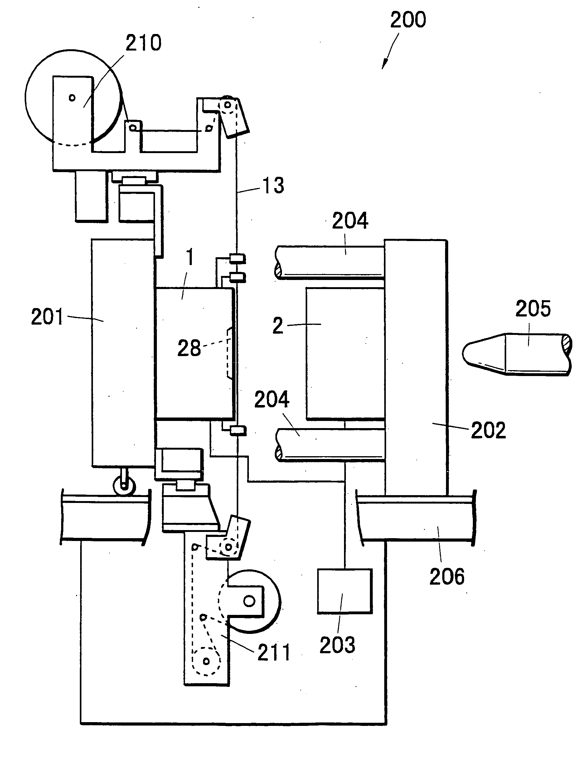
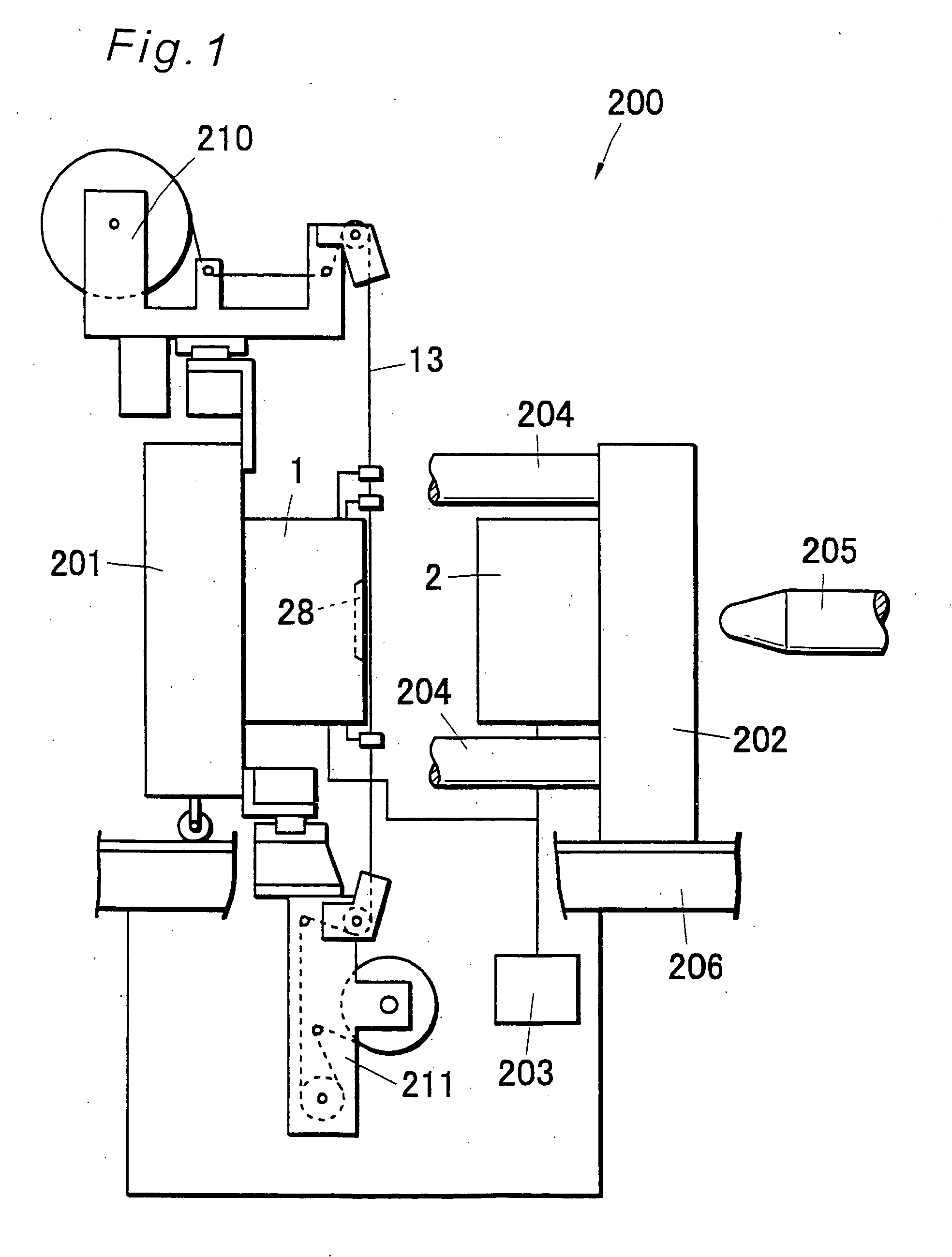
[0066]FIG. 1 is a view showing the outlined configuration of an in-mold decorating apparatus on which a mold for in-mold decoration according to a first embodiment of the present invention is mounted. As shown in FIG. 1, an in-mold decorating apparatus 200 is composed of a movable-side mold 1 mounted on a movable plate 201, a stationary-side mold 2 mounted on a stationary plate 202, and an injection nozzle 205 for injecting molten resin to a cavity formed between both the molds.

[0067] In the present embodiment, the stationary plate 202 is fixed to a frame 206, and a tie bar 204 fixed to the stationary plate 202 guides the movable plate 201, which moves so as to come into contact with or go away from the stationary plate 202.

[0068] By moving the movable plate 201, the parting face of the stationary-side mold 2 and the parting face of the movable-side mold 1 are brought into tight contact with each other, which forms a closed mold state in which molding portions of the molds (a cavi...

second embodiment

[0132] Description is now given of molds for in-mold decoration according to a second embodiment of the present invention.

[0133] Molds for in-mold decoration 101, 102 shown as the second embodiment in FIG. 19 and FIG. 23 are the molds for use, for example, in the in-mold decorating apparatus shown in FIG. 1, which are purposed to fulfill molding and decoration processes simultaneously on the surface of a thin plate-shaped molded article. A movable-side mold 101 shown in FIG. 19 and a stationary-side mold 102 shown in FIG. 23 are each composed of cavity-forming blocks 103, 131 having two pieces of molding-use cavities 128, 138 into which a decorating film is inserted and mounts 107, 110 each for fixing two pieces of the cavity-forming blocks 103, 131.

[0134] In the molds 101, 102 according to the present embodiment, such pockets for fitting the nests thereinto as would be provided in the prior art are not provided in the mounts while, instead, the mounts and the cavity-forming block...


PUM

PropertyMeasurementUnit
heightaaaaaaaaaa
clamping forceaaaaaaaaaa
thicknessaaaaaaaaaa

Abstract

A mold for in-mold decorating simultaneously with molding manufacturable at low cost in a short delivery period in manufacturing the mold and capable of stably mass-producing molded article in molding the molded articles, wherein cavity forming blocks having molding cavities into which an in-mold decoration film is to be inserted are mounted on diesets on a fixed side and a movable side. Pockets into which the cavity forming blocks are fitted are not formed in the diesets, the diesets and cavity forming blocks are positioned by engaging projections formed on one of the contact faces thereof and engaging recesses formed in the other before installation, and a plurality of mold clamping force receiving parts are installed on the outside of a film passing area around the cavity forming blocks.

Description

TECHNICAL FIELD [0001] The present invention relates to a mold for in-mold decoration which mold allows low price and short delivery period to be realized in mold manufacture and which mold is excellent in thermal efficiency in its molding process. BACKGROUND ART [0002] Conventionally, as a method for decorating a surface of a molded article made of resin, there has been an in-mold decoration method including the steps of continuously feeding a printed or otherwise worked decorating film into a mold, and integrating the printed layer with the molded article surface by resin pressure and heat in the molding process. For this use, the mold for in-mold decoration is given by one in which a so-called mold base, which is a standardized item for mold-parts supply manufacturers, is used according to standard types for general molding-use metal molds, where a molding-use cavity is formed on mold release surfaces (parting surfaces) of the mold base. More specifically, the cavity is formed, i...

Claims


Application Information

Patent Timeline
Patent Type & Authority Applications(United States)
IPC IPC(8): B29C45/00B29C45/14B29C45/26
CPCB29C45/14016B29C45/2675B29C45/2606B29C45/14827B29C33/30B29C45/14B29C45/26
Inventor TOYOOKA, NAOTOOZAWA, MITSUHIRO
Owner NISSHA PRINTING COMPANY
Learn More