Solid oxide fuel cell cathode comprising lanthanum nickelate

a solid oxide fuel cell and lanthanum nickelate technology, which is applied in the direction of cell components, applications, ceramicware, etc., can solve the problem of low current density

Inactive Publication Date: 2007-08-09
THE UNITED STATES OF AMERICA AS REPRESENTED BY THE SECRETARY OF THE NAVY
View PDF5 Cites 38 Cited by
  • Summary
  • Abstract
  • Description
  • Claims
  • Application Information

AI Technical Summary

Problems solved by technology

Few materials exhibit the catalytic, electrical and mechanical properties required for high activity and durability in a high power density solid oxide fuel cells (SOFCs) cathode.
However, below 800° C., the overpotential of LSM electrodes on YSZ is significant, resulting in low current densities.

Method used


Image

  • Solid oxide fuel cell cathode comprising lanthanum nickelate
  • Solid oxide fuel cell cathode comprising lanthanum nickelate
  • Solid oxide fuel cell cathode comprising lanthanum nickelate

Examples


example 1

[0034] Synthesis of La2NiO4+δ—La2NiO4+δ was synthesized Using a combustion technique adapted from the literature. A solution was prepared with 0.95 M glycinec (98.5%, Alfa) mixed with 0.3 M lanthanum(III) nitrate (99.99%, Alfa) and 0.15 M nickel(II) nitrates (99.9985%, Alfa) in 18 mΩ·cm water. The solution was evaporated on a hot plate from a beaker with stirring at 90° C. for several hours until it violently ignited, leaving an amorphous, black powder. For safety, less than 100 mL in an 800 mL beaker was used for each combustion reaction, and worked in a closed hood. The amorphous powder was ground in an agate mortar and then heated in air at 5° C. / min to 1100° C. and held for 2 h before cooling to room temperature at 5° C. / min. The purity of the La2NiO4+δ phase was confirmed by X-ray diffraction and matching to JCPDS reference 34-0314. SEM (Leo Supra55) showed LN agglomerates less than 1 μm in diameter.

example 2

[0035] Single cell testing—The suitability of LN as a SOFC cathode has only been reported in ex situ tests and on “symmetrical cells” with two air electrodes.28,31 The objective of this example was to confirm the suitability of LN as a SOFC cathode by evaluating it in full “dime” cells under an air / H2 gradient. The LN was evaluated as a stand-alone MIEC, and in bi-layer composite cathodes. With this approach, measured performance was interpreted based on available out of cell property measurements.

[0036] Anode-supported SOFC “dime cells” 2.6 cm in diameter were prepared at the University of Utah using previously developed methods.3 The anodes were 0.5 to 1 mm thick and the YSZ electrolyte was 8 μm thick. To make the cathode interlayer, ethylene glycol slurries of LN, SDC (Praxair), or 50:50 LN:SDC were ball milled with YSZ milling balls for 12 h. The final LN particle size was 0.2 μm, and the SDC particle size was about 0.5 μm. The slurries were painted in a 1 cm2 disk onto the YSZ...

example 3

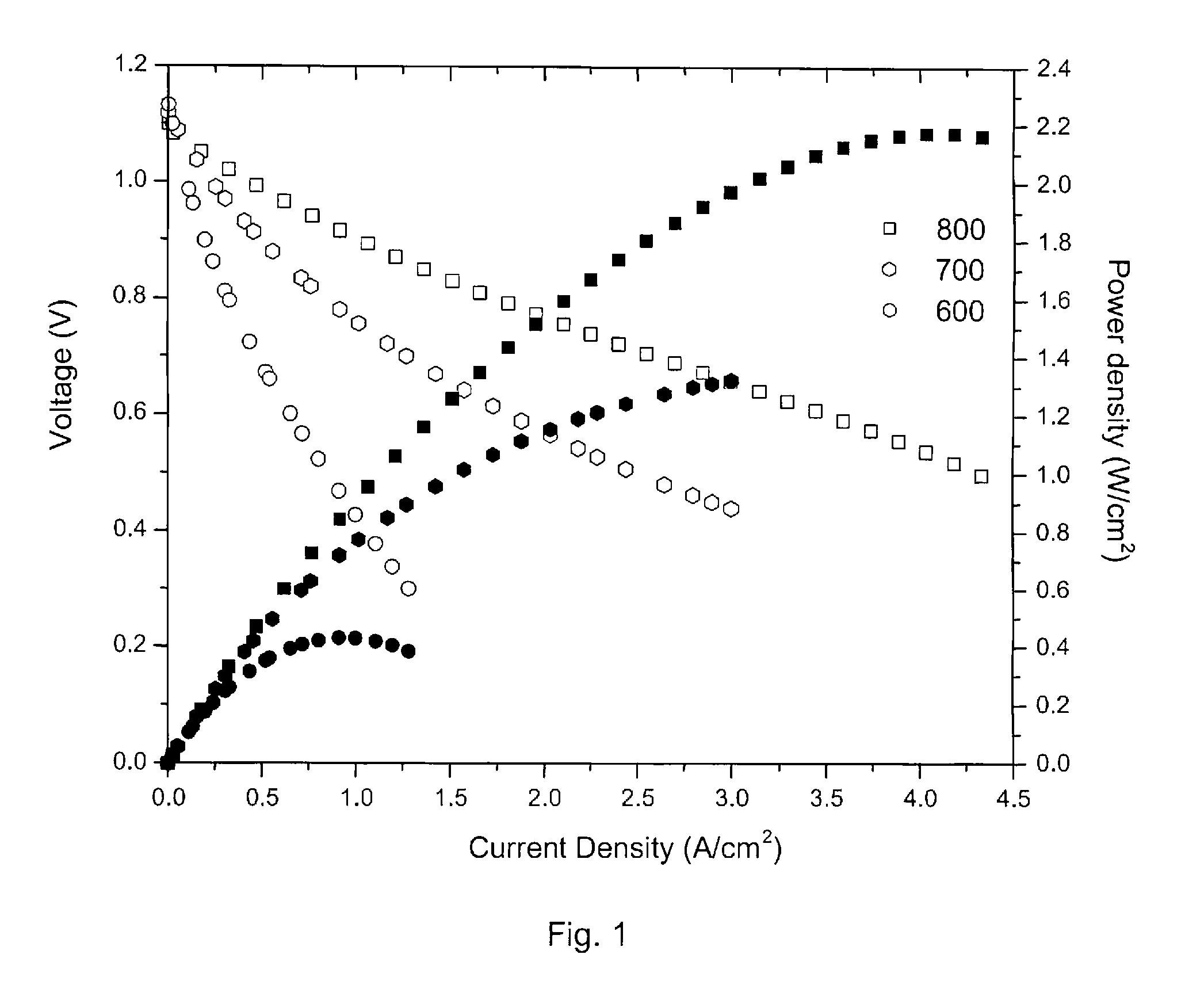
[0046] Temperature testing—FIG. 5 shows the performance of a cell having a porous 10-20 μm thick interlayer of (La2NiO4+δ+SDC) and a porous 50 μm thick current collector of LSC tested at 600, 650, 700, 750, and 800° C. The maximum power density (MPD) was ˜1.96 W / cm2 at 800° C., ˜1.5 W / cm2 at 750° C., ˜1 W / cm2 at 700° C., ˜0.55 W / Cm2 at 650° C., and ˜0.28 W / cm2 at 600° C.

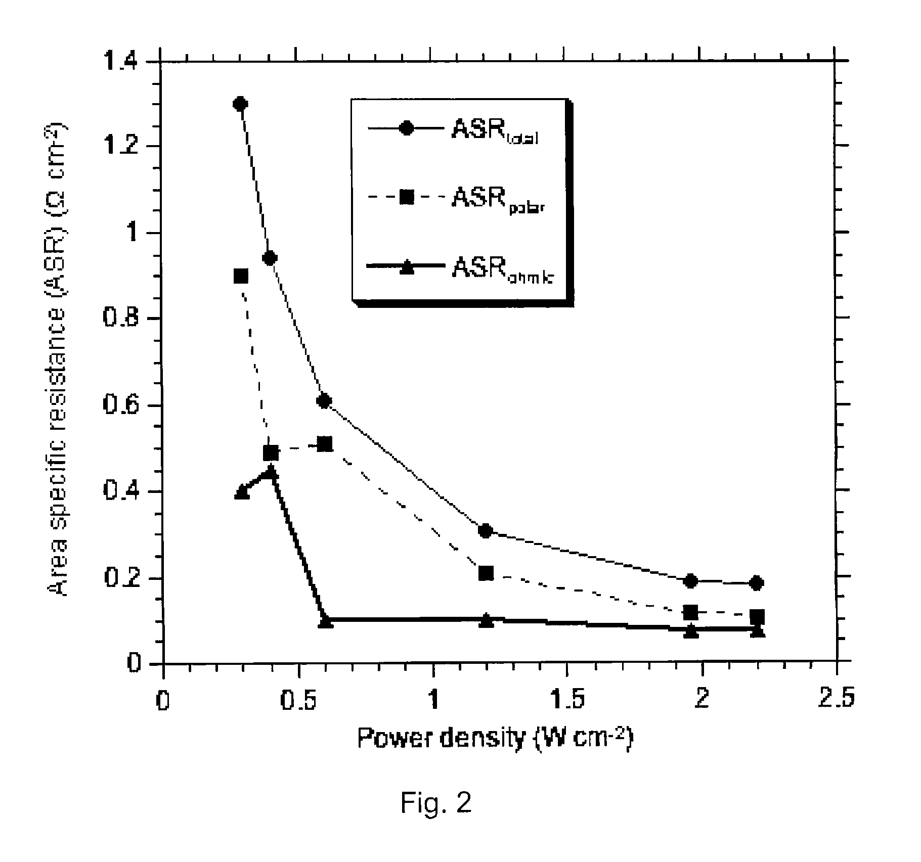
[0047] The results of the area specific ohmic resistance (ASR) measured by current interruption on this cell are reported on FIG. 6 for various temperatures. As seen in this figure, the ASR increased with decreasing temperature; the ASR increased from 0.076 to 0.4 Ω·cm2 with the decrease of temperature from 800° C. to 600° C. The ASR increased from 0.085 Ω·cm2 at 800° C. to 0.15 Ω·cm2 at 600° C. for an optimized cell with the following materials set: LSM, YSZ, Ni.


PUM

PropertyMeasurementUnit
temperatureaaaaaaaaaa
thickaaaaaaaaaa
thickaaaaaaaaaa

Abstract

A solid mixture of La2NiO4+δ and an ionic conductive material. A solid oxide fuel cell having a cathode interlayer having a La2NiO4+δ layer and a doped ceria layer, a lanthanum strontium cobaltite or lanthanum strontium manganate cathode current collector, an anode; and an ionic conductive electrolyte between and in contact with the cathode interlayer and the anode.

Description

[0001] This application claims the benefit of U.S. Provisional Patent Application No. 60 / 762,223, filed on Jan. 26, 2006, incorporated herein by reference.FIELD OF THE INVENTION [0002] The invention relates generally to compositions comprising lanthanum nickelate and fuel cells made therefrom. DESCRIPTION OF RELATED ART [0003] Few materials exhibit the catalytic, electrical and mechanical properties required for high activity and durability in a high power density solid oxide fuel cells (SOFCs) cathode. Up to 60% of voltage loss in anode-supported SOFCs can occur at the cathode, particularly at 800° C. and lower temperatures, due to polarization losses associated with the oxygen reduction reaction (ORR) for the reduction of oxygen gas to oxygen ions, O2− (Eq. 1).1 (All referenced publications and patent documents are incorporated herein by reference.).O2+4e−=2O2−  (1)[0004] State of the art SOFCs utilize porous composite cathodes whereby the ORR primarily occurs at the three-phase-b...

Claims


Application Information

Patent Timeline
Patent Type & Authority Applications(United States)
IPC IPC(8): H01M8/12C04B35/50H01M8/04
CPCC04B35/48C04B35/488C04B38/0074C04B2111/00853H01M4/9033H01M8/0217Y02E60/50H01M8/04268H01M2008/1293Y02E60/525H01M8/04007
Inventor LYONS, KAREN SWIDERLABERTY, CHRISTELZHAO, FENGVIRKAR, ANIL V.
Owner THE UNITED STATES OF AMERICA AS REPRESENTED BY THE SECRETARY OF THE NAVY
Why Eureka
Try Eureka