
Retention assembly for a hydrocarbon trap

a technology of hydrocarbon traps and assembly parts, applied in the direction of hose connections, cleaning using liquids, separation processes, etc., can solve the problems of unsatisfactory noise or even damage to the trap, maximizing the efficiency of the trap, undesired noise, etc., and achieve the effect of reducing hydrocarbon emissions

Active Publication Date: 2007-08-16
MANN HUMMEL GMBH
View PDF5 Cites 23 Cited by
  • Summary
  • Abstract
  • Description
  • Claims
  • Application Information

AI Technical Summary

Benefits of technology

[0015] A further object of the invention is to provide an efficient and secure hydrocarbon trap that is adapted to reduce hydrocarbon emissions over the lifetime of a motor vehicle.
[0022] In order to more easily insert the trap into the outlet duct, the outlet duct is preferably heated to a temperature greater than the temperature of the trap. At temperatures above room temperature, the dimensions of the outlet duct, which is preferably made of synthetic resin, expand to increase the tolerance between the outlet duct and the trap.

Problems solved by technology

Vibration may lead to undesired noise or even damage to the trap.
Furthermore, a snug fit within the outlet duct causes a majority of the gases passing through the outlet duct to pass through (rather than around) the hydrocarbon trap, thus maximizing its efficiency.
Thermal stresses acting upon an unsecured hydrocarbon trap can produce undesired results.
Because the dimensions of the synthetic resin outlet duct will increase more than the dimensions of the trap substrate, the snug fit between the outlet duct and the substrate will be compromised, which may result in undesired noise, adsorptive inefficiency and possibly permanent damage to the trap.

Method used


Image

  • Retention assembly for a hydrocarbon trap
  • Retention assembly for a hydrocarbon trap
  • Retention assembly for a hydrocarbon trap

Examples


Embodiment Construction

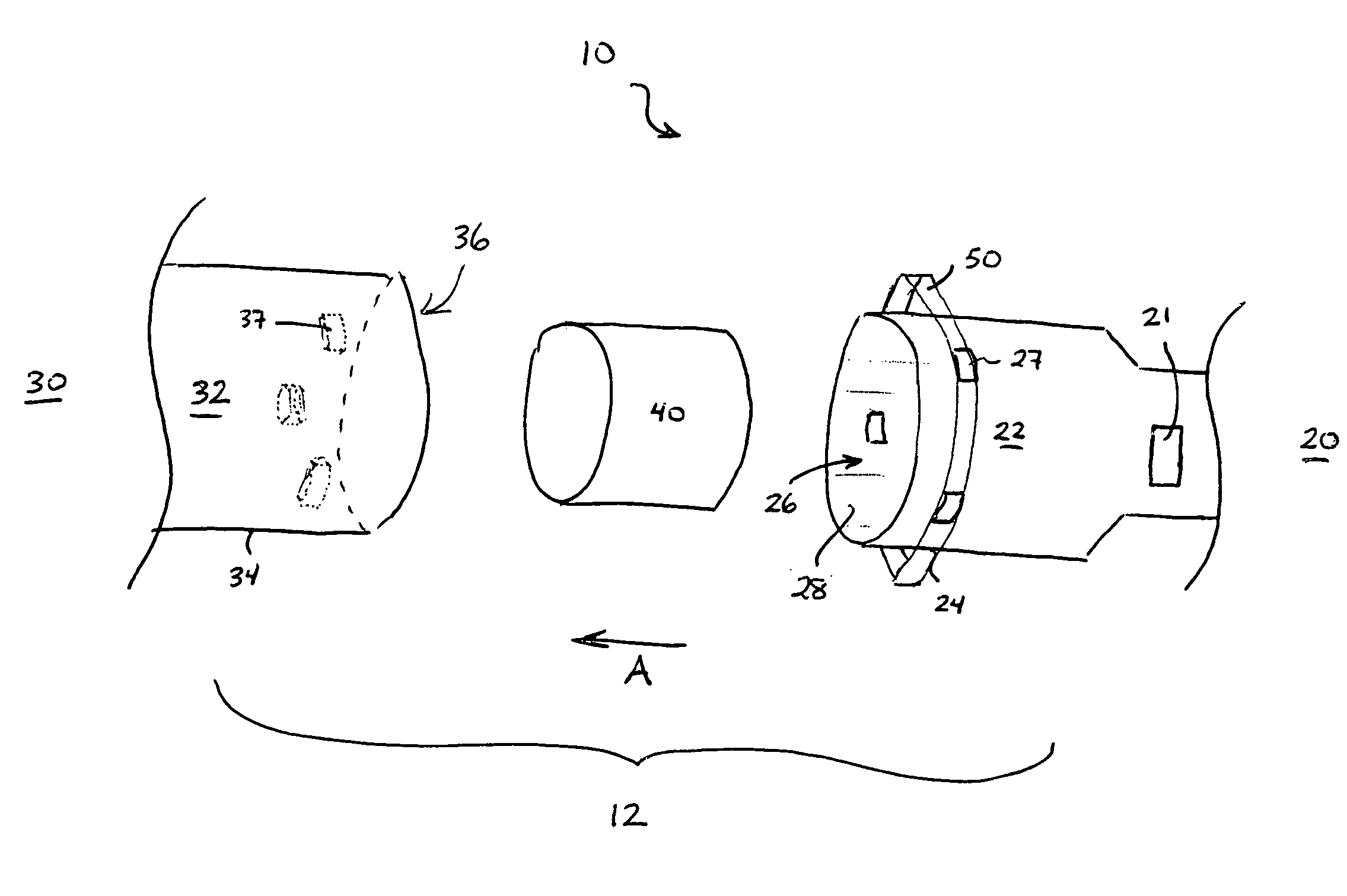
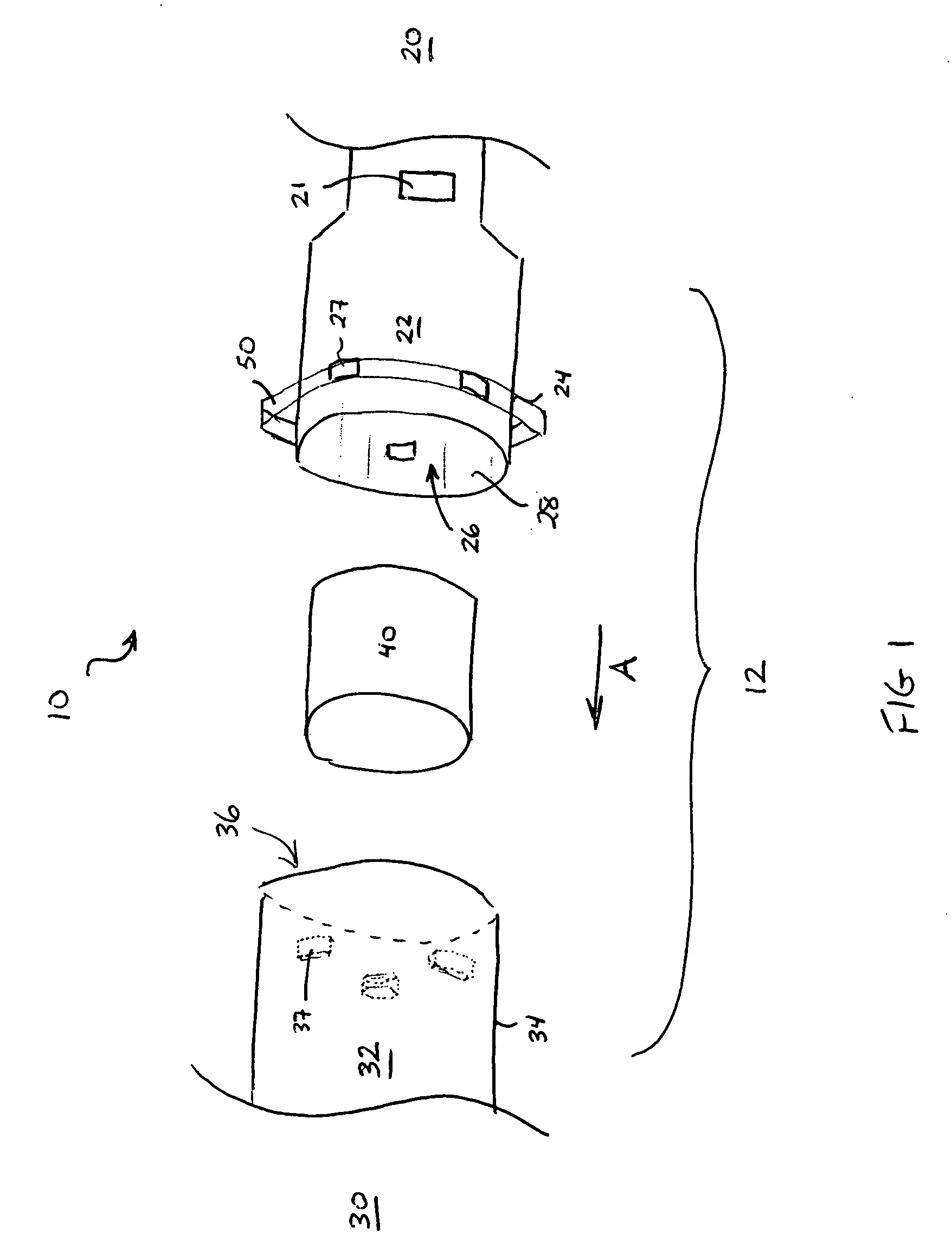
[0028] Referring to FIG. 1, an exploded perspective view of a portion of an air induction system 10 comprises a hydrocarbon trap retention assembly 12 installed in the vicinity of a motor vehicle engine (not shown). The air induction system functions to filter and meter the air intake flow into the engine.

[0029] The air induction system comprises an air cleaner 20 and a clean air duct 30. The air cleaner is connected to the clean air duct so that clean air that has been filtered by the air cleaner flows to the engine via the clean air duct. The direction of air flow through the air induction system (from the ambient to the engine) is shown by arrow A. Air cleaner 20 comprises an air cleaner outlet duct 22 located at a downstream side (engine side) thereof, and clean air duct 30 comprises a clean air duct inlet 32 located at an upstream side thereof The air induction system 10 may further comprise a mass air flow sensor 21. The mass air flow sensor (MAFS) can be positioned downstrea...


PUM

PropertyMeasurementUnit
thicknessaaaaaaaaaa
widthaaaaaaaaaa
widthaaaaaaaaaa

Abstract

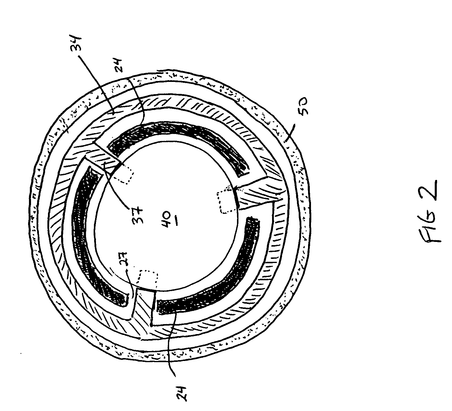
A retention assembly secures a hydrocarbon trap within an air intake path of an internal combustion engine. The hydrocarbon trap is positioned within a first air tube, such as an outlet duct of a clean air filter. A second air tube, such as an inlet portion of a clean air duct assembly, is fitted over a portion of the first air tube to enclose the hydrocarbon trap within the first air tube. A clamp is fitted over both the first and second air tubes. A plurality of radially-extending, circumferentially-spaced protrusions that are formed on an inner surface of the second air tube pass through a respective plurality of apertures formed in the first air tube and, under radial compression exerted by the clamp, engage an outer surface of the hydrocarbon trap, thereby securing the trap within the first air tube.

Description

BACKGROUND OF THE INVENTION [0001] 1. Field of Invention [0002] A retention assembly for a hydrocarbon trap is incorporated into an air induction system of a motor vehicle having a combustion engine in order to secure the trap and reduce hydrocarbon emissions. [0003] 2. Description of Related Art [0004] Under the increasingly stringent California LEV (Low Emission Vehicle) II standards and United States Environmental Protection Agency (EPA) Tier II standards, automakers are required to dramatically reduce the amount of evaporative emissions from their gasoline-powered vehicles (by 75% for California's LEV II program and by 52.5% for the EPA's Tier 2 program). By 2007, all gasoline-powered vehicles will be required to meet these standards for evaporative emissions. [0005] Evaporative emissions are hydrocarbon (HC) vapors that come from sources in a motor vehicle other than the exhaust system. Major sources of evaporative emissions include a motor vehicle's air intake system, fuel rai...

Claims


Application Information

Patent Timeline
Patent Type & Authority Applications(United States)
IPC IPC(8): B08B3/00
CPCB01D53/0415B01D2259/4516F02M25/0854F02M33/04F02M35/02F02M35/10347F02M35/024F02M35/10019F02M35/10144F02M35/10281F02M35/10321F02M35/021
Inventor BRAITHWAITE, ALEXWILLIG, MICHAELPFEIFFER, FRANKMAIER, STEFAN
Owner MANN HUMMEL GMBH
Learn More