Delay alignment in a closed loop two-point modulation all digital phase locked loop

a closed loop, delay alignment technology, applied in the field of data communication, can solve problems such as degradation of transmitter performan

Inactive Publication Date: 2007-08-16
TEXAS INSTR INC
View PDF6 Cites 58 Cited by
  • Summary
  • Abstract
  • Description
  • Claims
  • Application Information

AI Technical Summary

Benefits of technology

[0019]There is further provided in accordance with the present invention, a apparatus for alignment of two-point data modulation injection in a digital phase locked loop (DPLL) comprising a reference clock domain for reference point injection of modulation data into the loop, a direct clock reference clock domain for direct point injection of the modulation data into the loop and delay alignment means for aligning the reference clock domain with and the direct clock domain in the reference clock domain utilizing interpolative correlation means to precisely tune delay adjustments associated with the reference point injection and the direct point injection resulting in the alignment of both the reference clock domain and the direct clock domain.

Problems solved by technology

In particular, for GSM / EDGE modulations the AM / PM alignment needs to be better than 10 nanoseconds, otherwise a degradation in the transmitter performance occurs.

Method used


Image

  • Delay alignment in a closed loop two-point modulation all digital phase locked loop
  • Delay alignment in a closed loop two-point modulation all digital phase locked loop
  • Delay alignment in a closed loop two-point modulation all digital phase locked loop

Examples


first embodiment

[0103]A block diagram illustrating a WCDMA transmitter having precise delay alignment between amplitude and frequency modulation paths is shown in FIGS. 17A and 17B. The transmitter, generally referenced 220, comprises a pulse shaping filter 222, CORDIC and polar signal processing 223 which splits the data into amplitude and phase modulation paths. The amplitude modulation path comprises gain normalizer 224, AM-AM predistortion 226, digital delay adjustment 228, encoder and dynamic element matching (DEM) 230, digital ΣΔ modulator 234 and digital power amplifier (DPA) 256. The phase modulation path comprises AM-PM predistortion 276, phase interpolation 274, exception handler 272, ADPLL loop 270, encoder and DEM 264, digital ΣΔ modulator 268, DCO 262, quad switch 258, digital delay adjustment 246 and quad sync 254.

[0104]In accordance with the invention, the transmitter also comprises a clock divider array comprising divider chains 238, 240, 242. Clock divider chain 242 functions to di...

second embodiment

[0119]A block diagram illustrating a WCDMA transmitter having precise delay alignment between amplitude and frequency modulation paths is shown in FIGS. 19A and 19B. The transmitter, generally referenced 290, comprises a pulse shaping filter 292, CORDIC and polar signal processing 294 which splits the data into amplitude and phase modulation paths. The amplitude modulation path comprises gain normalizer 296, AM-AM predistortion 298, digital delay adjustment 300, encoder and dynamic element matching (DEM) 302, digital ΣΔ modulator 306 and digital power amplifier (DPA) 316. The phase modulation path comprises AM-PM predistortion 348, phase interpolation 346, exception handler 344, ADPLL loop 342, encoder and DEM 336, digital ΣΔ modulator 340, DCO 334, quad switch 332 comprising TDL 328, digital delay adjustment 318 and quad sync 326.

[0120]In accordance with the invention, the transmitter also comprises a clock divider array comprising divider chains 314, 312, 310. Clock divider chain ...

third embodiment

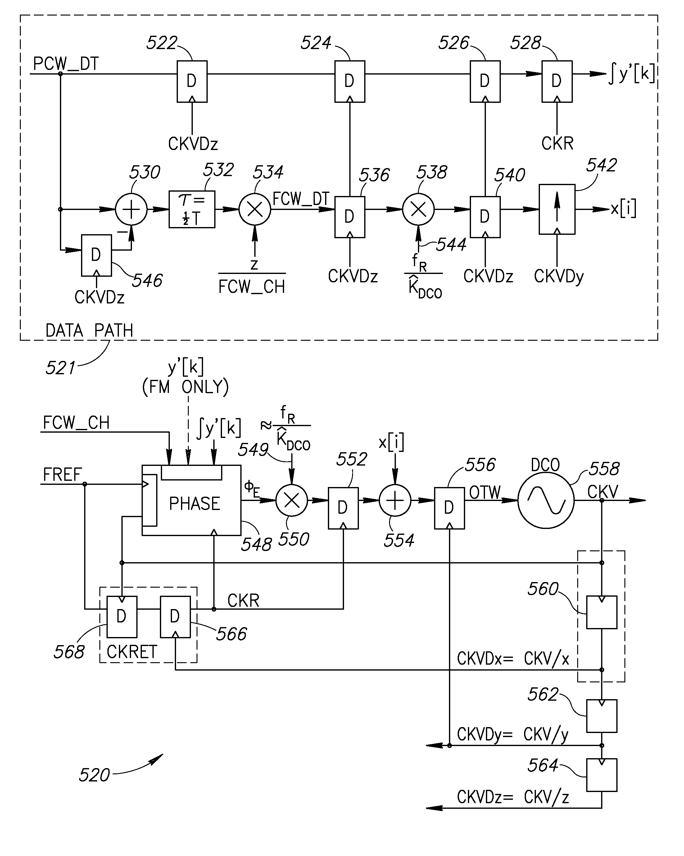
[0136]The Figure illustrates the phase / frequency modulation path in the third generation DRP (i.e. third embodiment). It adds support for the high data rates of the WCDMA and WLAN standards by dramatically increasing the frequency modulating bandwidth. The maximum bandwidth limitation of fR / 2 in DRP1 and DRP2 architectures is broken here by employing CKV-down-divided clocks in the final stages of the modulating path. Since the modulating sample rate is much higher now than the CKR clock, the modulating stream is merged with the ADPLL phase / frequency corrections just before the DCO input.

[0137]The key features of the architecture are described below. First, the ADPLL phase operation is performed on the CKR clock. Second, in order to reduce circuit complexity and save dissipated power, the pulse-shaping filter at the front-end of the modulating path operates at the lower CKVDz rate, where z is an integer. The FCW-normalized samples are then resampled to the CKR rate for the y′[k] comp...


PUM


Abstract

A novel apparatus for and method of delay alignment in a closed loop two-point modulation all digital phase locked loop (ADPLL). The invention provides a fully digital delay alignment mechanism where better than nanosecond alignment is achieved by accounting for processing delays in the digital circuit modules of the transmitter and by the use of programmable delay elements spread across several clock domains. Tapped delay lines compensate for propagation and settling delays in analog elements such as the DCO, dividers, quad switch, buffers, level shifters and digital pre-power amplifier (DPA). A signal correlative mechanism is provided whereby data from the amplitude and phase/frequency modulation paths to be matched is first interpolated and then cross-correlated to achieve accuracy better than the clock domain of comparison. Within the ADPLL portion of the transmitter, precise alignment of reference and direct point injection points in the ADPLL is provided using multiple clock domains, tapped delay lines and clock adjustment circuits.

Description

REFERENCE TO PRIORITY APPLICATION[0001]This application claims priority to U.S. Provisional Application Ser. No. 60 / 773,759, filed Feb. 15, 2006, entitled “Scheme To Achieve Precise Delay Alignment Between Amplitude And Phase / Frequency Modulation Paths In Digital Polar Transmitters And For Closed Loop Two-Point Modulation At Different Injection Rates In ADPLL”, incorporated herein by reference in its entirety.FIELD OF THE INVENTION[0002]The present invention relates to the field of data communications and more particularly relates to an apparatus for and method of delay alignment in a closed loop two-point modulation all digital phase locked loop (ADPLL).BACKGROUND OF THE INVENTION[0003]Modern complex envelope modulation schemes such as Enhanced Data rates for GSM Evolution (EDGE), Wideband Code Division Multiple Access (WCDMA), Bluetooth Enhanced Data Rate (BT-EDR), Wireless Local Area Network (WLAN), Worldwide Interoperability for Microwave Access (WiMAX), etc. impose strict perfo...

Claims


Application Information

Patent Timeline
Patent Type & Authority Applications(United States)
IPC IPC(8): H03D3/24H04L27/04
CPCH03C3/0991H03C5/00H03L2207/50H04L27/3818H03C3/0966H03C3/0933H03C3/0941H03C3/095H03C3/0925
Inventor WAHEED, KHURRAMFOO, TIMSTASZEWSKI, ROBERT B.
Owner TEXAS INSTR INC
Why Eureka
Try Eureka