Fuel cell system having a fuel cell, a hydrogen storage tank, and an anode circuit

Inactive Publication Date: 2007-08-16
DAIMLER AG
View PDF10 Cites 15 Cited by
  • Summary
  • Abstract
  • Description
  • Claims
  • Application Information

AI Technical Summary

Benefits of technology

[0008] Another advantage of the present invention is derived in that the tank pressure charger always supplies a substantial amount of energy when a substantial amount of hydrogen is required. Generally, this condition coincides with a likewise greater volumetric flow rate of recirculated anode waste gas. It is thus inherent to the system that the use of the pressure energy from the tank is optimized in terms of the anode recirculation requirement.
[0009] One very advantageous refinement of the present invention provides for the bearings of the turbine and especially for the bearings of the tank pressure charger as well, in the case of a turbine and pumping device mounted on one shaft, to be designed as gas bearings.
[0010] Another refinement provides for these gas bearings to be designed as hydrogen bearings. Thus, the sealing problem is completely circumvented

Problems solved by technology

In this context, due to the low mass flow rate of hydrogen, the available pressure energy from the hydrogen storage tank does not suffice for delivering all of the cathode air.
Common to both DE 101 54637 A1 and DE 36 04 618 A1 is also the disadvantage that very complex s

Method used


Image

  • Fuel cell system having a fuel cell, a hydrogen storage tank, and an anode circuit
  • Fuel cell system having a fuel cell, a hydrogen storage tank, and an anode circuit
  • Fuel cell system having a fuel cell, a hydrogen storage tank, and an anode circuit

Examples


Embodiment Construction

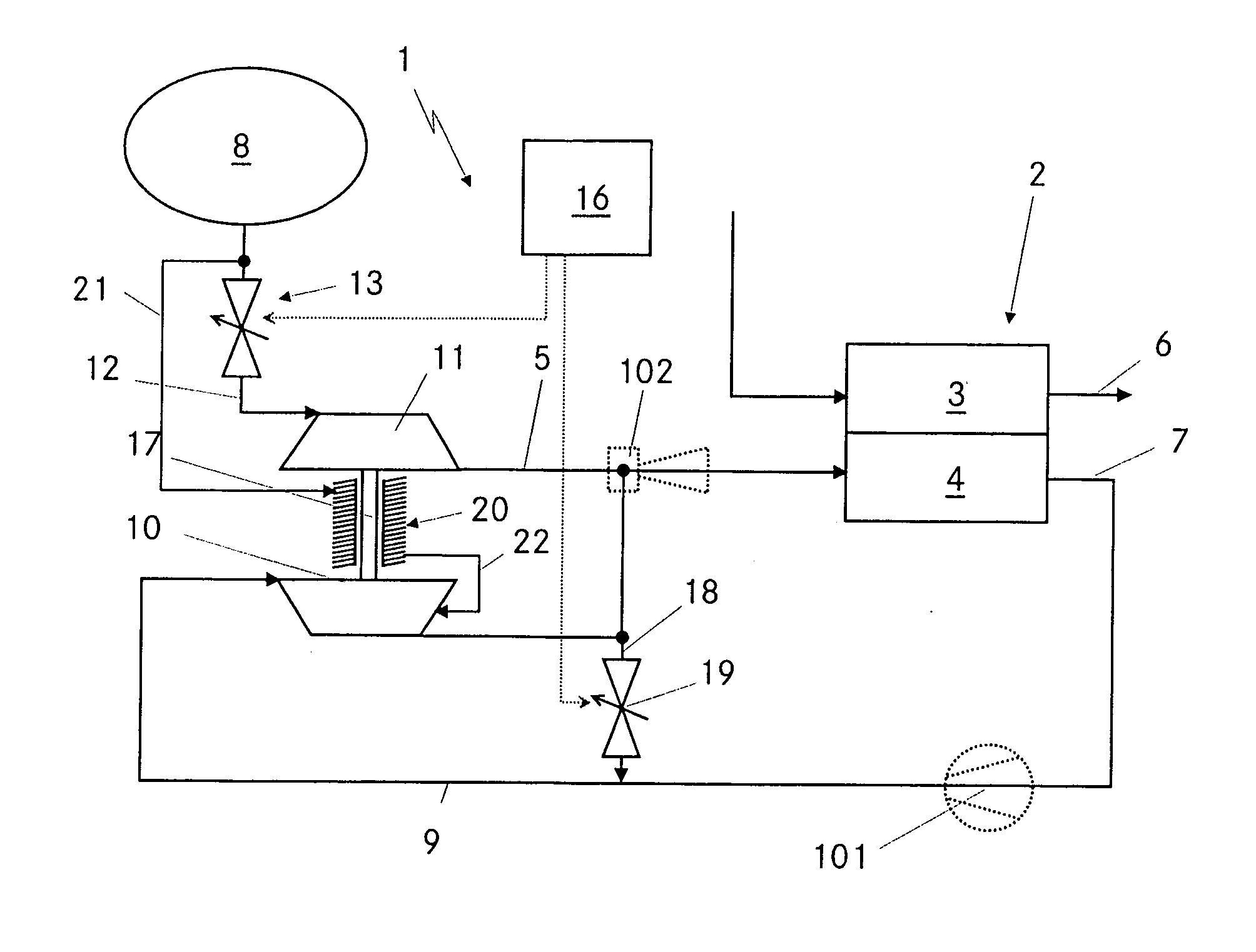
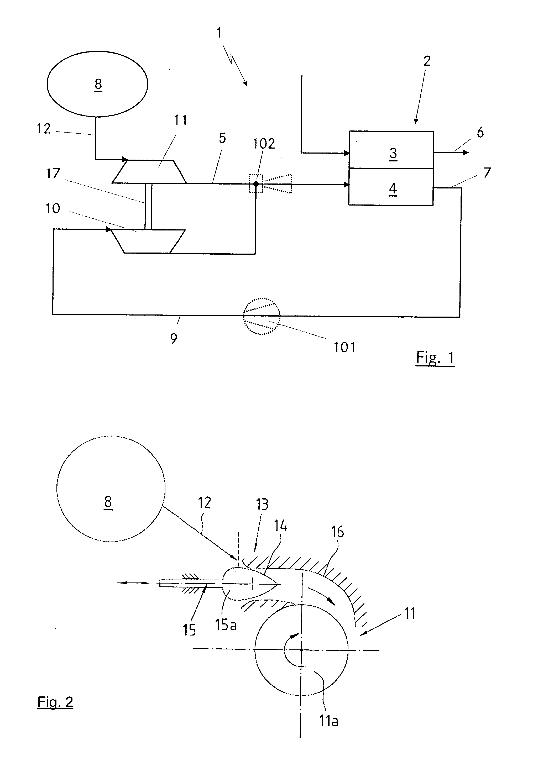
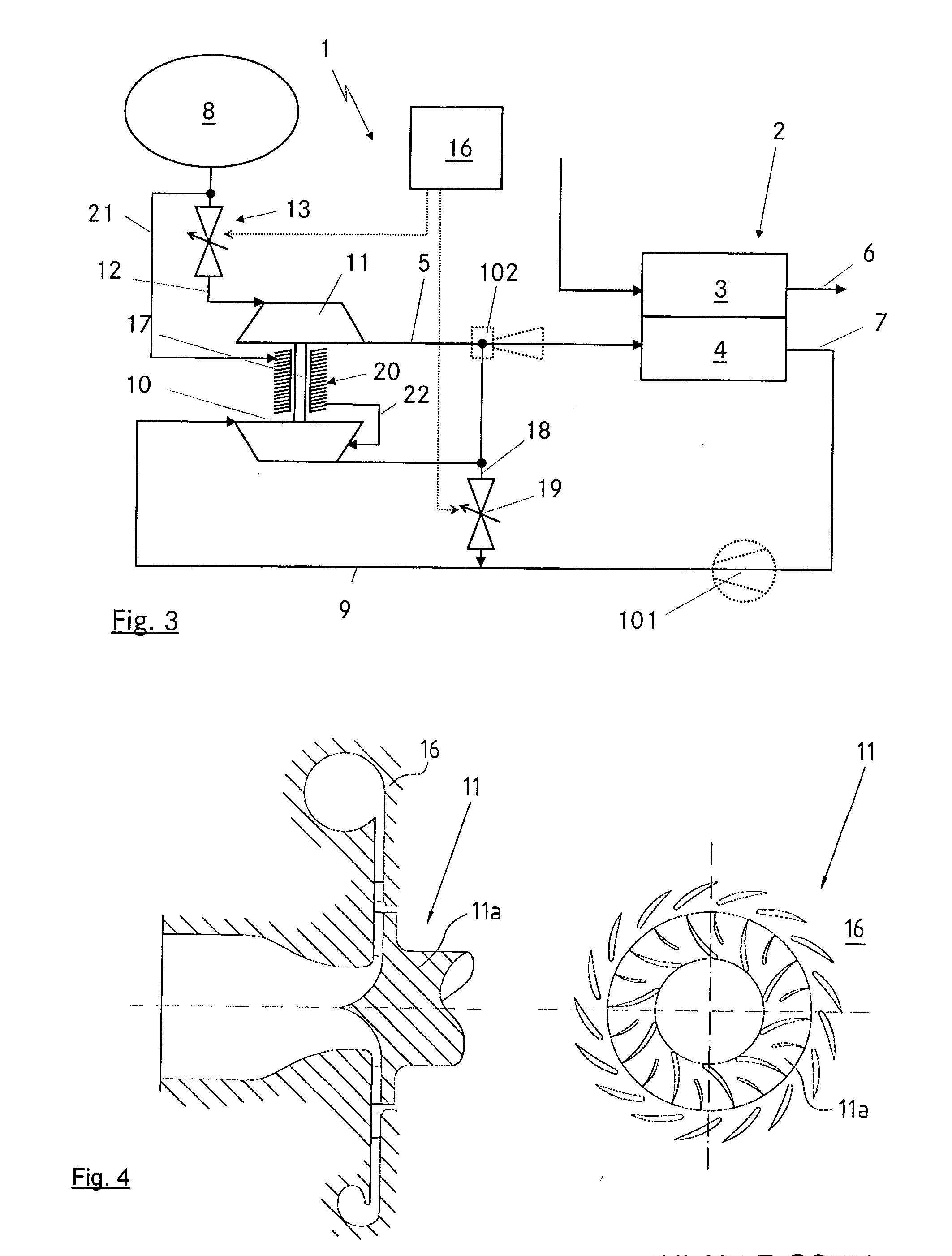
[0020] A fuel cell system 1 is shown exemplarily in FIG. 1. Fuel cell unit 2 contained therein includes a plurality of fuel cells which are preferably configured in a stack, and in which case one or more fuel cell stacks may be electrically connected in series and / or in parallel, in order to supply a desired voltage and current level for electrical consumers. Fuel cell unit 2 is illustrated in a simplified representation by a cathode 3 and an anode 4. Cathode 3 is supplied in a manner known per se via a cathode-side supply line with an oxidizing agent, for example air, while anode 4 is supplied via an anode-side supply line 5 with a reducing agent, typically hydrogen. The reducing agents and oxidizing agents react with one another in the fuel cells of fuel cell unit 2, and reaction products are purged via cathode-side and anode-side purging lines 6, 7. The reaction, i.e. conversion, produces an electrical voltage in fuel cell unit 2 that may be used to supply electrical consumers, i...


PUM


Abstract

A fuel cell system has at least one fuel cell, a hydrogen storage tank in which hydrogen is stored at a pressure above atmospheric and which communicates via a hydrogen supply line with an anode chamber of the fuel cell. An anode circuit, via which unreacted hydrogen is able to be recirculated from a region downstream of the anode chamber into the hydrogen supply line, is provided. At least one pumping device is provided between the outlet of the anode chamber and its inlet in the anode circuit and/or the hydrogen supply line. Between the hydrogen storage tank and the anode chamber, a turbine is provided, which supplies at least a portion of the power required for driving the pumping device.

Description

[0001] Priority is claimed to German Patent Application No. DE 10 2006 003 799.5, filed Jan. 25, 2006, the entire disclosure of which is hereby incorporated by reference herein. BACKGROUND [0002] The present invention relates to a fuel cell system having at least one fuel cell, a hydrogen storage tank, as well as an anode circuit. [0003] From the German Patent Application DE 101 54637 A1, it is known to utilize the pressure energy contained in a hydrogen storage tank of a fuel cell system by employing a turbine to compress air that is directed to the cathode of the fuel cell. In this context, due to the low mass flow rate of hydrogen, the available pressure energy from the hydrogen storage tank does not suffice for delivering all of the cathode air. [0004] A comparable approach for fuel cells having aqueous electrolyte is described by German Patent Application DE 36 04 618 A1. It likewise provides for utilizing pressure energy from the hydrogen tank to circulate the electrolyte. [00...

Claims


Application Information

Patent Timeline
IPC IPC(8): H01M8/04
CPCH01M8/04097H01M8/04111H01M8/04201Y02E60/50H01M2250/20Y02T90/32H01M8/04208Y02T90/40
Inventor HINSENKAMP, GERTSTUTE, MANFREDSUMSER, SIEGFRIED
Owner DAIMLER AG
Why Eureka
Try Eureka