
Separator for fuel cell, manufacturing method thereof, and fuel cell having such a separator

Active Publication Date: 2007-08-16
DOOSAN CORP
View PDF2 Cites 18 Cited by
  • Summary
  • Abstract
  • Description
  • Claims
  • Application Information

AI Technical Summary

Benefits of technology

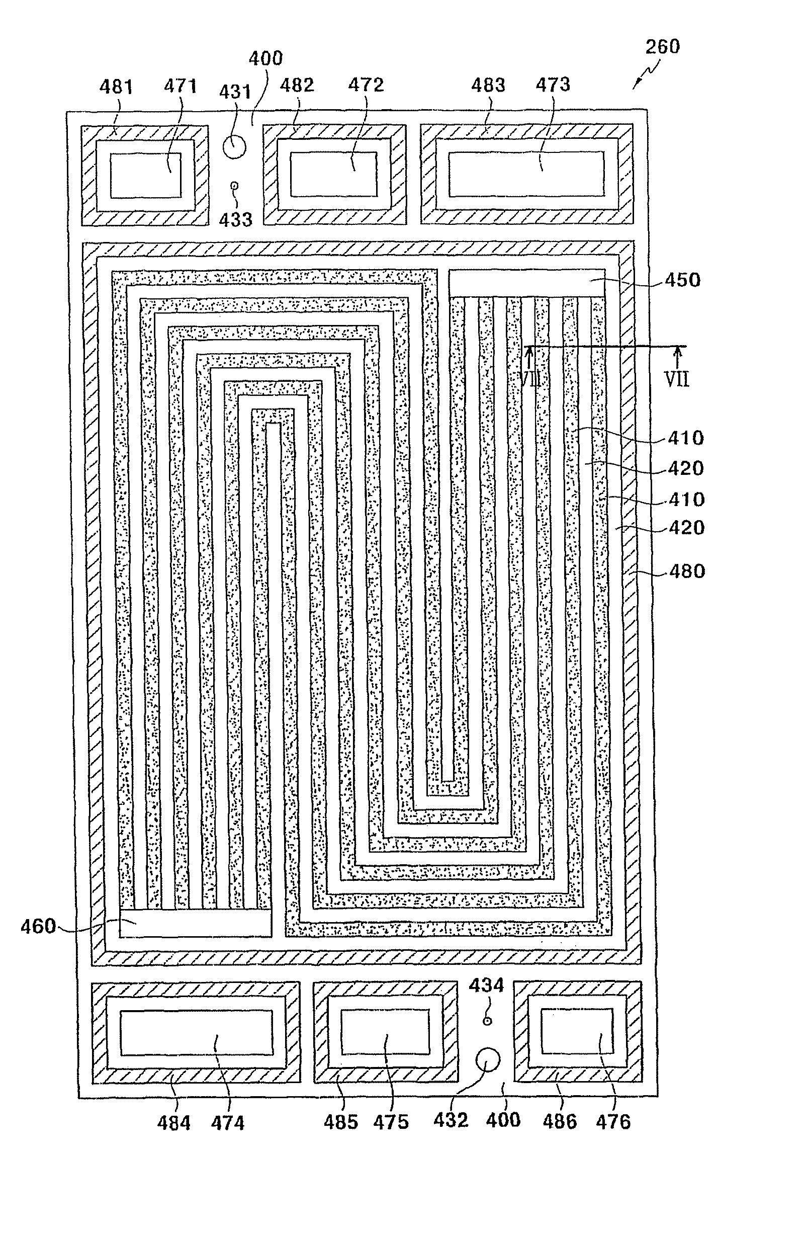
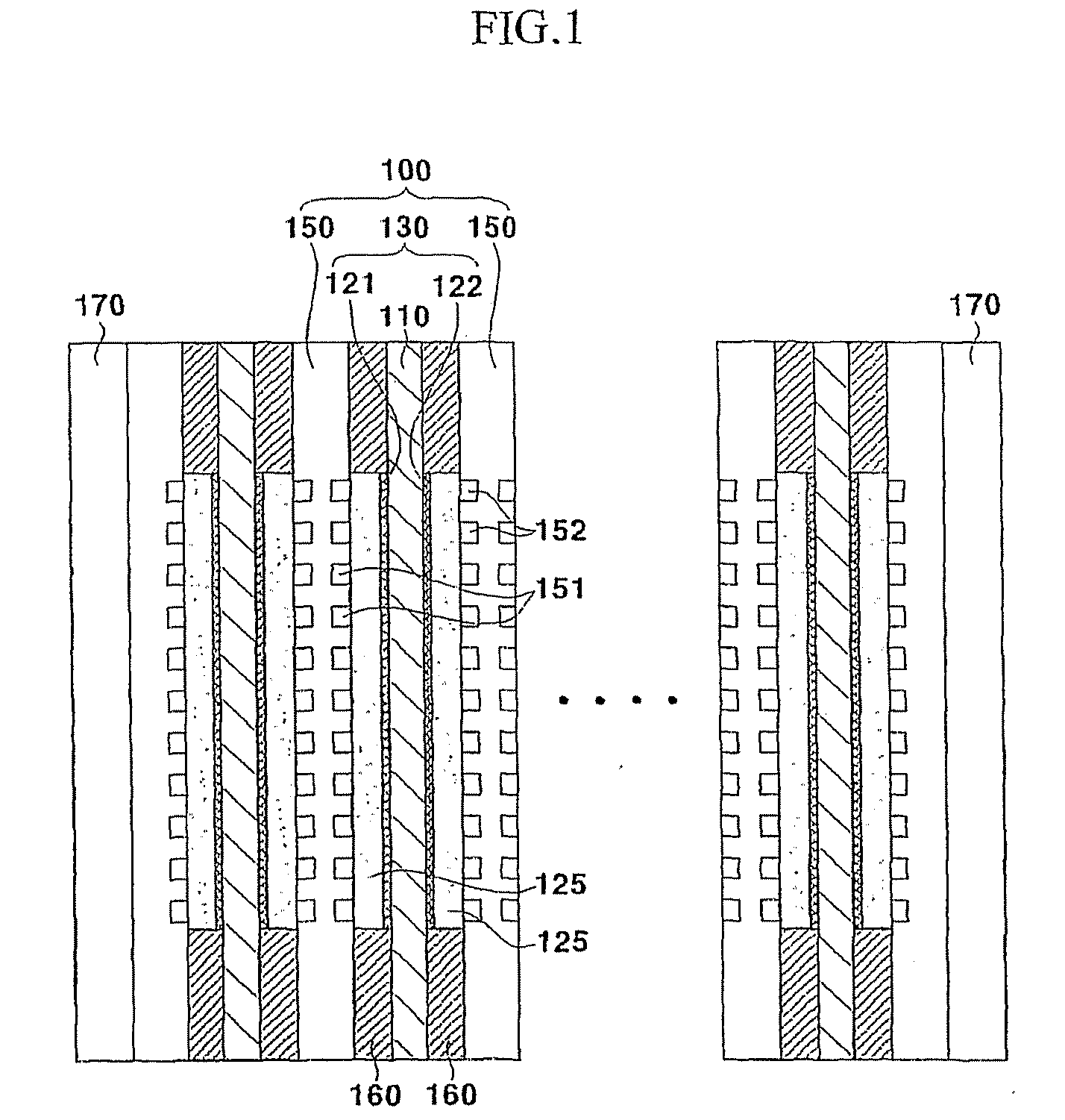
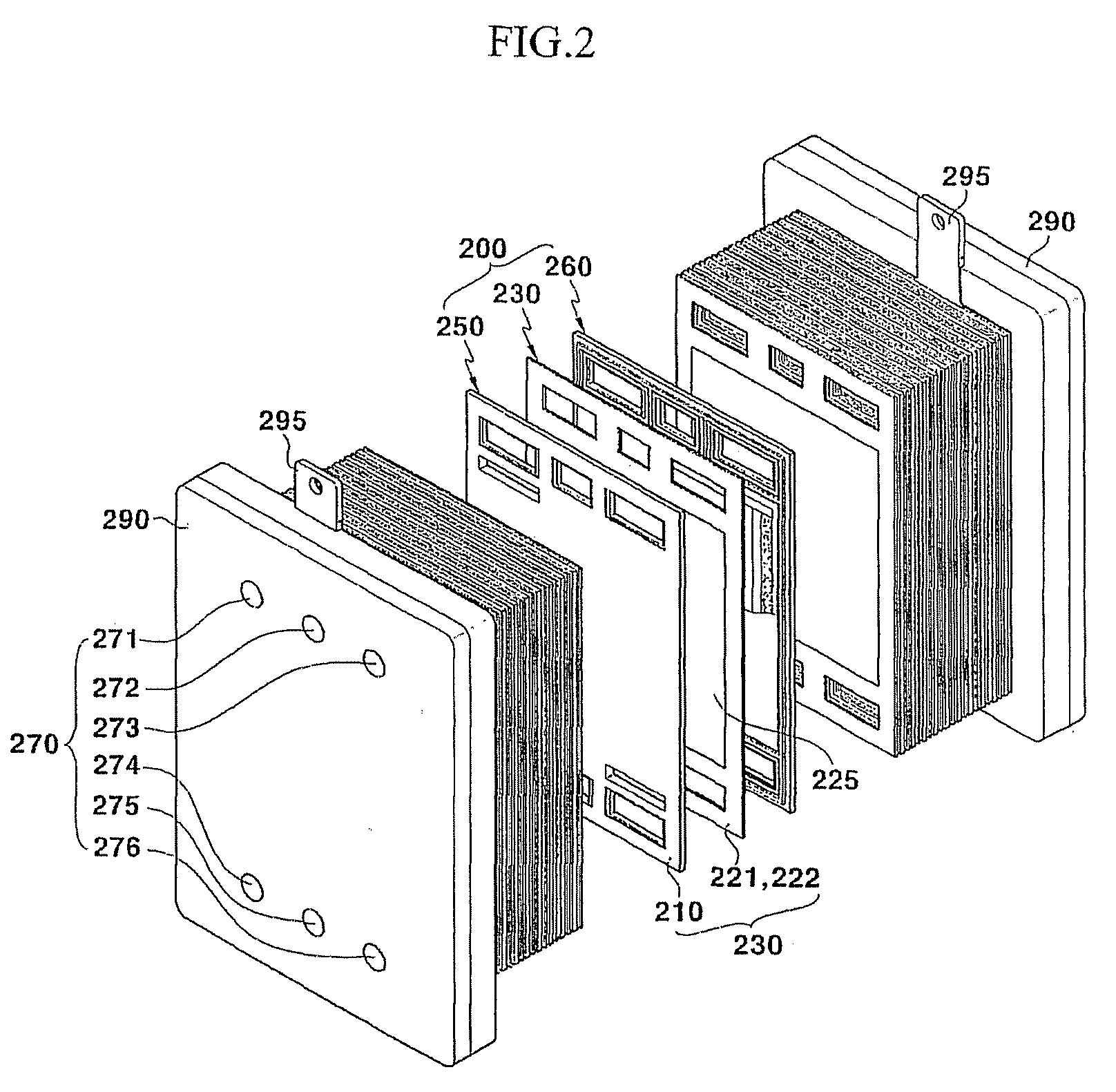
[0024] Therefore, the present invention has been made in an effort to solve the above-described problem. The motivation for the present invention is to provide a separator for a fuel cell, a manufacturing method thereof, and a fuel cell including such a separator, providing an enhanced water exhaust performance, enhanced durability, and being more appropriate for mass production.

Problems solved by technology

When the polymer electrolyte membrane is not sufficiently hydrated, ion conductivity of the polymer electrolyte membrane is lowered, and therefore performance of a fuel cell is deteriorated.
To the contrary, when the polymer electrolyte membrane is excessively hydrated, small pores forming a triple-phase boundary of reaction are blocked (which is usually called flooding), and thereby the reaction area of the electrodes reduces, resulting in deterioration in performance of the fuel cell.
Therefore, in the case that the water formed at cathodes is not promptly exhausted, reaction gas is not sufficiently supplied to the catalyst layer, and therefore performance of a fuel cell is deteriorated.
In addition, liquefied water requires a high pressure of reduction gas for exhaust thereof.
Therefore, energy loss occurs by a pressure drop of reduction gas between entry and exit of flow fields, and reaction gas is much consumed for stable realization of the reduction reaction at a high flow speed.
However, the resin included in the separator causes an increase of volume resistance with respect to movement of electrons, and thereby deteriorates performance of a fuel cell.
According to the prior art, the manufacturing process for a stable and useful separator using a graphite or a carbon composite material has been very complex, non-productive, and non-efficient.

Method used


Image

  • Separator for fuel cell, manufacturing method thereof, and fuel cell having such a separator
  • Separator for fuel cell, manufacturing method thereof, and fuel cell having such a separator
  • Separator for fuel cell, manufacturing method thereof, and fuel cell having such a separator

Examples


second embodiment

[0182] Hereinafter, the present invention related to the case that the graphite foil used for the separator includes a stainless steel layer therein is described with reference to FIG. 11.

[0183]FIG. 11 is a sectional view of FIG. 6 along a line XI-XI according to a second embodiment of the present invention.

[0184] As shown in FIG. 11, a lamellar structure graphite foil 1140 used for a separator 1150 according to a second embodiment of the present invention includes a stainless steel layer 1160 therein.

[0185] Such graphite foil 1140 including the stainless steel layer 1160 may be easily manufactured e.g., by pressing graphite layers of predetermined thickness to front and rear of the stainless steel layer 1160.

[0186] The stainless steel layer 1160 may be of, e.g., SUS304 or SUS316, and its thickness t is preferably 0.1 mm to 0.3 mm. The thickness d3 of the graphite layers formed at front and rear sides of the stainless steel layer 1160 is preferably more than 0.2 mm considering th...

first embodiment

[0188] A method for manufacturing the separator 1150 using the graphite foil 1140 including the stainless steel layer 1160 therein is the same as a method for manufacturing the separators 250 and 260 according to the present invention that has been described with reference to FIG. 10.

[0189] In the process of dry-etching for forming the flow-field channels 610, the graphite layer is etched such that the stainless steel layer 1160 is exposed. As for the process of dry-etching (e.g., the above-described sand blasting etching process), the stainless steel layer 1160 has a substantially smaller etch rate than the graphite layers formed to front and rear of the stainless steel layer 1160. Therefore, such stainless steel layer 1160 functions as an etch stop in the process of etching.

[0190] According to such a feature, the manufacturing process of a separator becomes easier, and a manufacturing device of lower precision may be used to produce a separator with equally high performance and p...


PUM


Abstract

A lamellar structure graphite foil is used as a material for a separator for a fuel cell, and a hydrophobic layer is formed by impregnation on flow-field channels of the graphite foil. Such a separator is manufactured by forming the flow field channel by etching the graphite foil formed with the mask pattern thereon and forming a hydrophobic layer by impregnation. According to such a separator, performance of a fuel cell stack is enhanced and the manufacturing process of a separator is simplified.

Description

BACKGROUND OF THE INVENTION [0001] (a) Field of the Invention [0002] Generally, the present invention relates to a fuel cell. More particularly, the present invention relates to a separator for a fuel cell using a graphite foil, a manufacturing method thereof, and a fuel cell stack including such a separator. [0003] (b) Description of the Related Art [0004] As is well known in the art, a fuel cell produces electric power by an oxidation reaction at an anode and a reduction reaction at a cathode. The anode and the cathode are formed with a catalyst layer having platinum or platinum-ruthenium metal for accelerating the oxidation and reduction reactions. [0005] At the anode, fuel gas (for example, hydrogen) is supplied thereto and is divided into ions (for example, protons) and electrons through the oxidation reaction. At the cathode, the divided ion bonds with a reduction gas (for example, oxygen) to form water. Final products of such reactions are electricity (i.e., electron movement...

Claims


Application Information

Patent Timeline
IPC IPC(8): H01M8/02H01M2/08H01M4/94H01M8/10H01B13/00H01M50/403
CPCY02E60/50H01M8/021H01M8/0286H01M8/0228H01M8/0263H01M8/1011H01M8/0213H01M8/0273Y02P70/50Y02E60/10H01M8/2483H01M8/0258H01M8/026H01M50/403H02J7/0044H01M8/0271H01M8/0223
Inventor KIM, HO-SUKHONG, BYUNG-SUNSHINN, MEE-NAM
Owner DOOSAN CORP
Learn More