
System and method for automatic taking of fluid samples

Inactive Publication Date: 2007-08-16
DATAINNOVATION I LUND
View PDF10 Cites 4 Cited by
  • Summary
  • Abstract
  • Description
  • Claims
  • Application Information

AI Technical Summary

Benefits of technology

[0009] The overall object of the present invention is to solve the problem of taking a fluid sample of a body fluid having the same composition as the body fluid at the sample site of the test object. An aspect of the object is to provide an automatic system for taking a fluid sample from a test object that minimizes the dilution of the taken sample.
[0011] By means of the present invention, several advantages are achieved as compared to the prior art. Amongst others, a taken fluid sample having a higher concentration as compared to a fluid sample taken by a prior art system is achieved. Another advantage is that a minimal amount of rinsing solution is supplied to the sample site reducing the dilution of the body fluid as compared to the prior art systems. Yet another advantage is that it provides an improved procedure for washing the lumens of the catheter means, whereby a drug solution can be supplied to the sample site by means of the same catheter means that is used for taking the sample with a minimized risk of contamination. SUMMARY OF THE INVENTION

Problems solved by technology

A drawback with some of the prior art system is that the volume of a taken sample usually is much larger than the volume necessary for the analysis of a taken sample.
Thus, if the taken sample is to be analyzed, the analysis would not give a representative result.
The unnecessary large volume that has to be taken is especially a drawback when taking blood samples from test objects, e.g. rats and mice, having a small total blood volume.
A drawback with this system is that one or several samples (reference numeral 62 in EP 0 389 719) is taken prior to the sample (reference numeral 63 in EP 0 389 719) that is to be analyzed in order to collect any residual of washing fluid that may remain in contact with the inner surface of the sample transfer tube.
Another drawback with the system is that the disclosed washing procedure (FIG. 2K in EP 0 389 719) causes all of the washing fluid flow to be directed through the catheter into the vessel of the living being.
Another drawback with supplying washing fluid to the vessel is that it changes the fluid balance of the living being.
Yet another drawback with supplying washing fluid to the vessel is that the washing fluid usually comprises heparin in order to prevent coagulation of blood in the catheter means but can be harmful to supply to the living being.

Method used


Image

  • System and method for automatic taking of fluid samples
  • System and method for automatic taking of fluid samples
  • System and method for automatic taking of fluid samples

Examples


Embodiment Construction

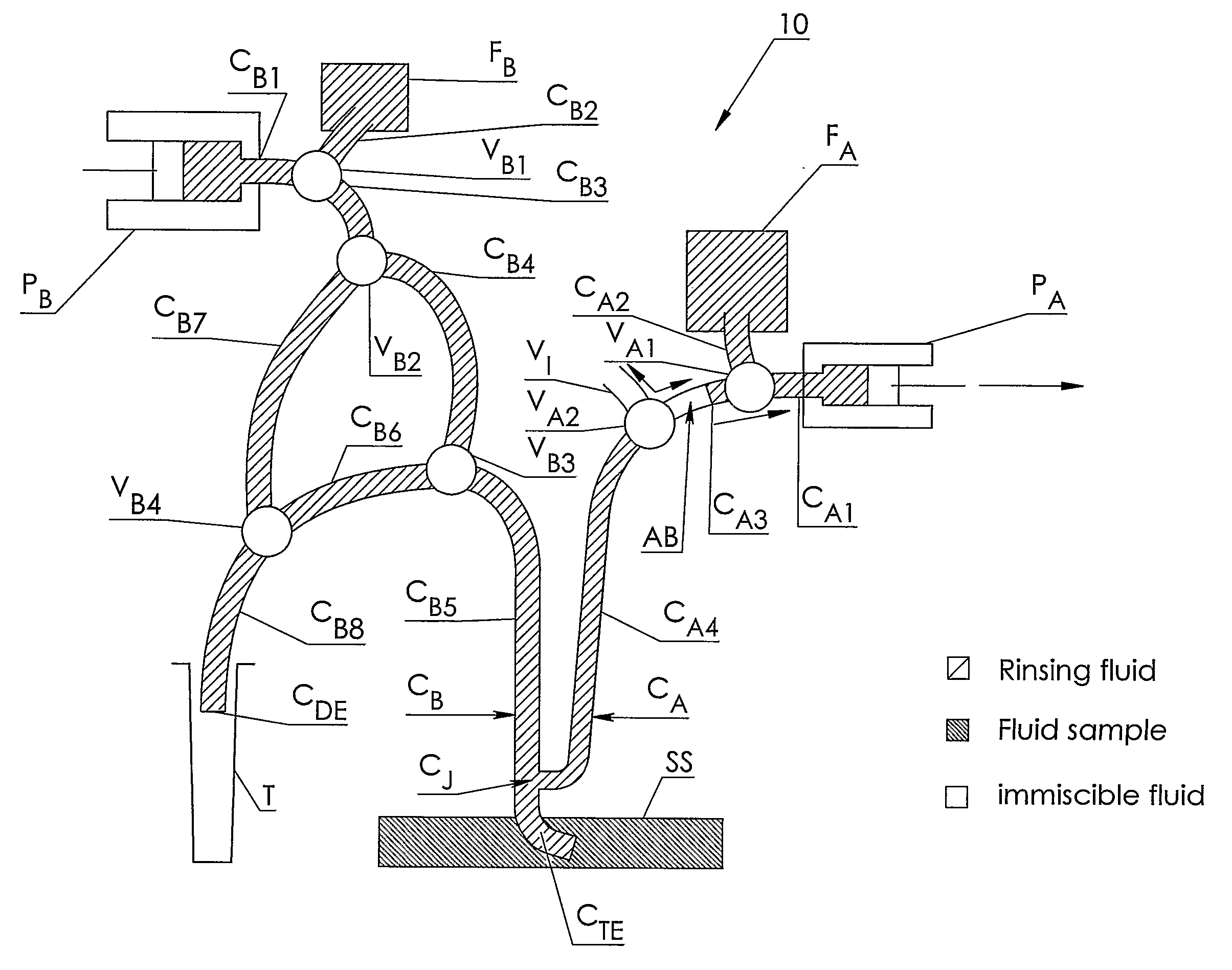
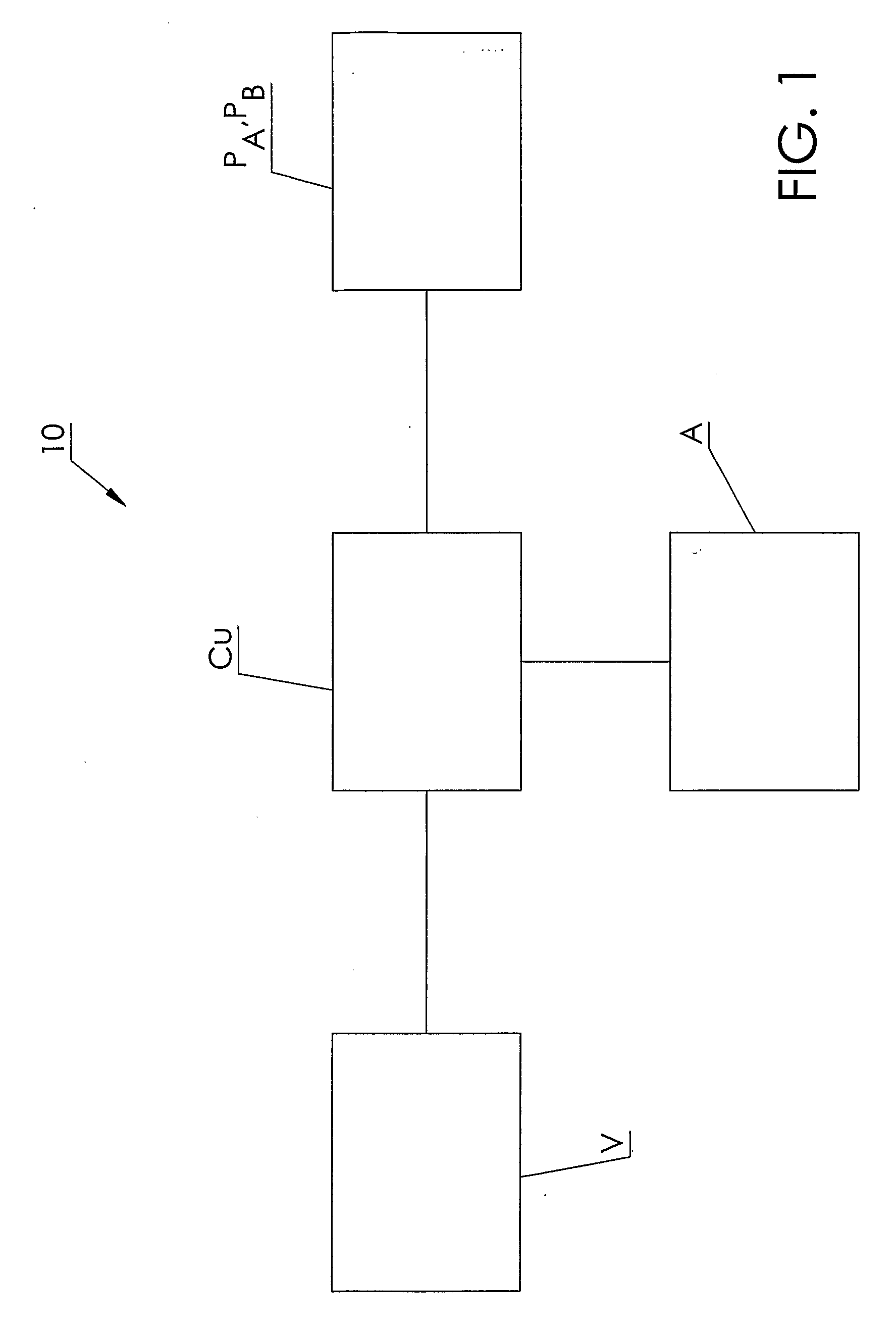
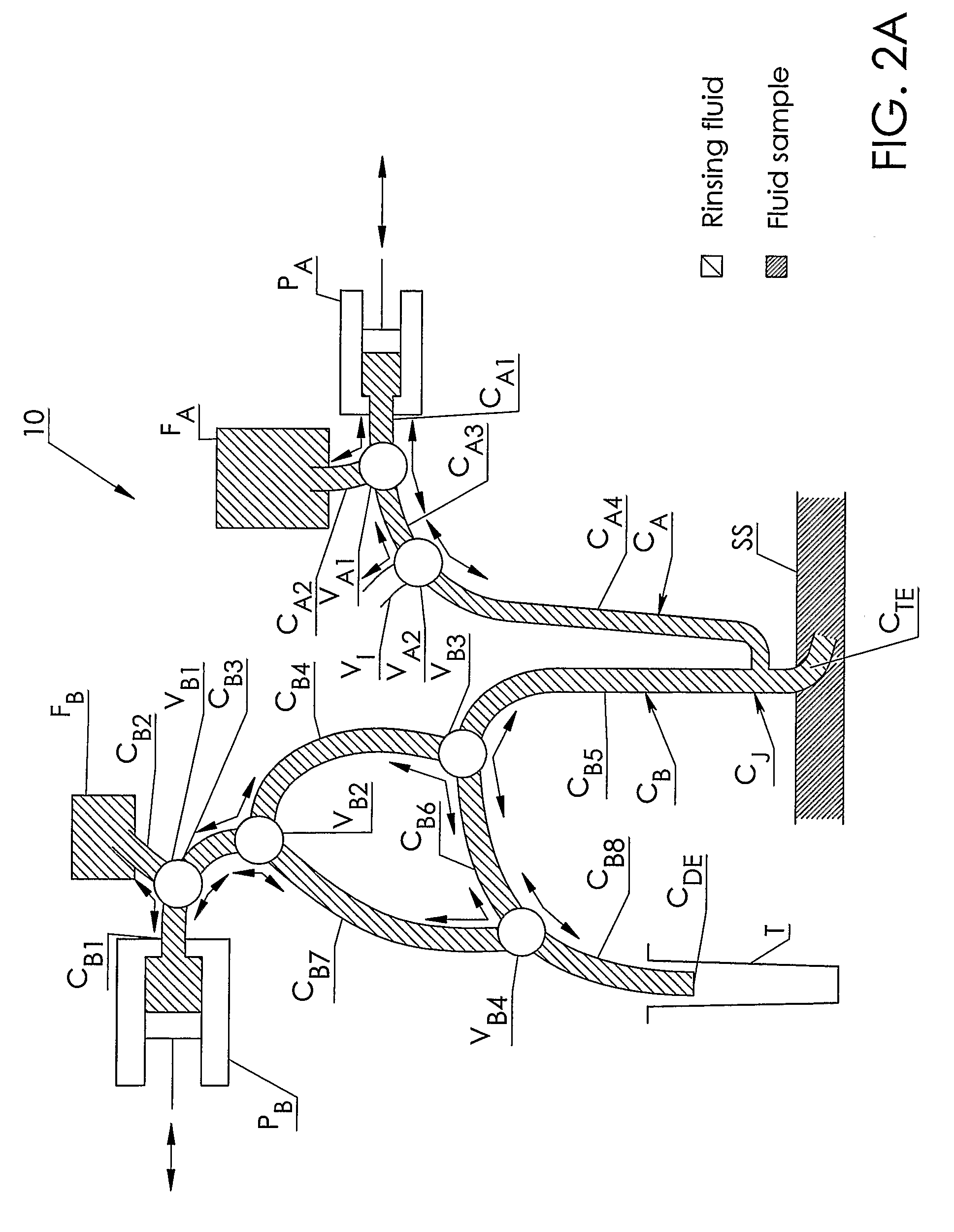
[0017] The present invention will now be described in more detail with reference to the accompanying drawings. FIG. 1 shows an embodiment of a system for automatic taking of specimens according to the invention. The figure schematically illustrates a control unit CU communicatively connected to pumping means PA, PB and a set of valves V. The control unit CU is configured to control the operation of the pumping means PA, PB and the set of valves V. The pumping means can for example be realized as a piston pump or a reciprocating pump. The system 10 according to the figure also comprises an analyzer A communicatively connected to the control unit CU. However, it should be understood that the analyzer can be a separate unit not comprised in the system 10 but instead connected to the system 10. The analyzer A is configured to analyze a taken sample.

[0018] As shown in the FIGS. 2A-2I, the system 10 comprises also flexible tubings, e.g. first and second catheter means CA and CB, respecti...


PUM


Abstract

The invention relates to automatic taking of fluid samples from a sample site (SS) of the living. A system comprises catheter means (CA,CB) having a junction (CJ) configured to be located in proximity to the sample site (SS). The junction is connected to first and second catheter means (CA,CB) and a sample-taking end (CTE). A valve (VA2) is connected to the first catheter means (CA) and has an inlet (VI) for an immiscible fluid to be aspirated into the first catheter means. Pumping means (PA,PB) are connectable to said catheter means and configured to aspirate and move said amount of said fluid (AB) to said junction. A first part (AB1) of said immiscible fluid (AB) is arranged in said second catheter means and a second part (AB2) in said first catheter means, whereby said first (AB1) and second (AB2) parts being configured to separate a taken sample (TS).

Description

TECHNICAL FIELD [0001] The present invention relates generally to automatic taking of fluid samples from a test object in the shape of a living being. More specifically, the invention relates to automatic taking of fluid samples having a composition representative of the composition of the fluid at the sample site of the living. BACKGROUND [0002] In medical science and pharmaceutical industry there is often a need to perform pharmacokinetic studies on living beings, for example test objects in the shape of laboratory animals such as rats and pigs. In such studies, it is common to take a plurality of samples or specimens from the test object as well as injecting substances into the test object during the course of hours or days, in order to allow observation of gradual responses in the test object. In order to minimize time and cost consuming manual handling of taking specimen as well as the stress impact of such a manual handling on the laboratory animal, attempts have been made to ...

Claims


Application Information

Patent Timeline
IPC IPC(8): A61B5/00A61M1/00A61M3/00A61D5/00A61B5/155G01N33/487
CPCA61B5/1427A61B5/15003A61B5/150099A61B5/150221A61B5/150229A61B5/150236A61B5/150992A61B5/153A61B5/155
Inventor HANSSON, HANS-AXEL
Owner DATAINNOVATION I LUND
Learn More