
Two-phase liquid cooling system with active venting

a liquid cooling system and active venting technology, applied in the direction of domestic cooling apparatus, semiconductor/solid-state device details, lighting and heating apparatus, etc., can solve the problems of cooling system cooling fluid boiling point, cooling system cooling fluid loss, etc., to achieve the effect of increasing the performance and reliability of the system

Inactive Publication Date: 2007-08-23
ISOTHERMAL SYST RES
View PDF27 Cites 51 Cited by
  • Summary
  • Abstract
  • Description
  • Claims
  • Application Information

AI Technical Summary

Benefits of technology

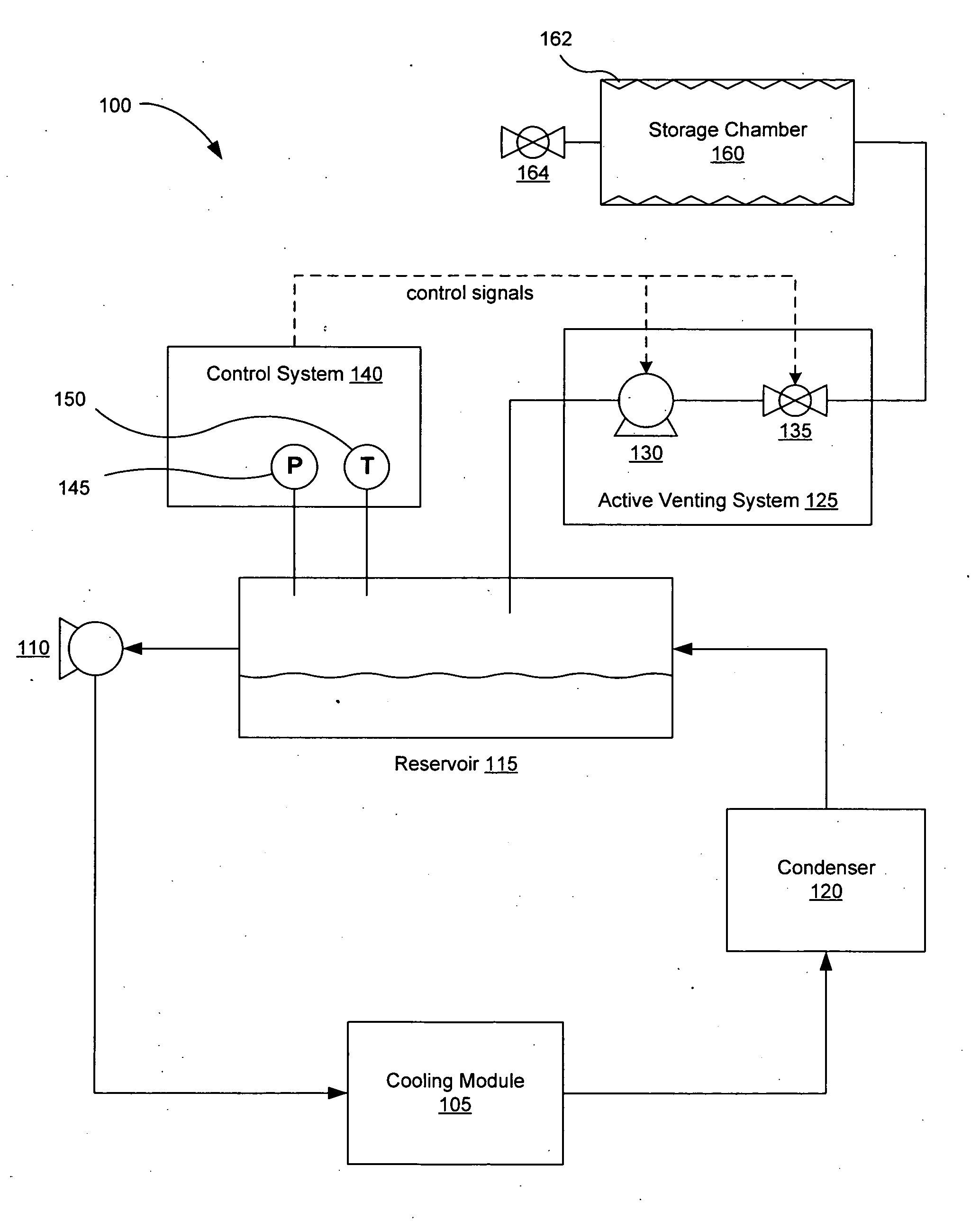
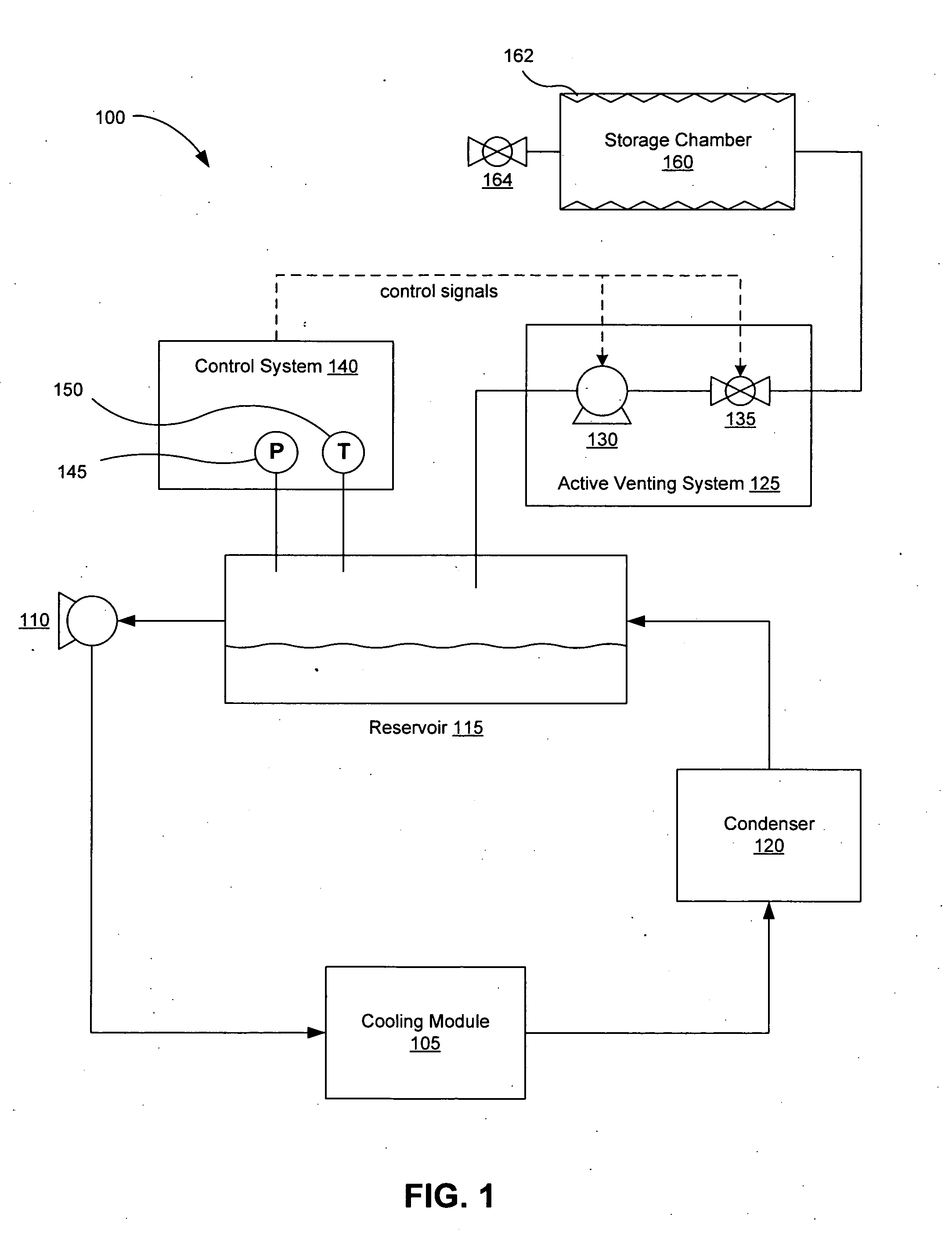
[0012] To avoid at least some of the problems encountered with existing two-phase liquid cooling systems, as described above, a cooling system with active venting is provided. An active venting system actively regulates the pressure within the cooling system, for example, by regulating the amount of non-condensable gases in the cooling system. With appropriate control of the active venting system, the performance and reliability of the system can be increased and maintained over long and continuous periods of operation.
[0014] The active cooling system can exhaust gases out of the system using various mechanisms. In one embodiment, a vent is located between the cooling module and the pump, and an auxiliary pump is coupled to the vent to pump a desired amount of gas out of the system. The control system is coupled to the auxiliary pump and vent to provide the ability to regulate the amount of gas removed from the system. The active venting system may also be capable of adding gases into the cooling system (e.g., by pumping air into the system) when a pressure increase is desired. In this way, the cooling system can regulate the pressure in the cooling system to achieve a desired overall cooling efficiency. Adding air to the cooling system may also help avoid cavitation in the pumps.

Problems solved by technology

Air is a common non-condensable gas in cooling systems, since they are typically run at pressures below atmospheric so that air tends to seep in slowly through points in the system that are not completely sealed or otherwise allow air permeation into the system.
The non-condensable gases cause a partial pressure within the closed volume of the cooling system, which alters the boiling point of the cooling fluid and thus affects the operation of the cooling system.
Otherwise, over time the cooling system would lose coolant and would need to have the coolant replaced.

Method used


Image

  • Two-phase liquid cooling system with active venting
  • Two-phase liquid cooling system with active venting
  • Two-phase liquid cooling system with active venting

Examples


Embodiment Construction

Two-Phase Cooling System with Active Venting

[0028]FIG. 1 illustrates one embodiment of a two-phase liquid cooling system 100 with active venting capabilities. The liquid cooling system 100 includes at least one cooling module 105, a pump 110, a reservoir 115, and a condenser 120. The pump 110 pressurizes a supply of liquid coolant from the reservoir 115 and delivers the liquid coolant to the cooling module 105. The cooling module 105 places the liquid coolant in thermal contact with a heat producing device (not shown), such as but not limited to computer processors, blade servers, circuit boards, memory, video cards, power devices, and the like. In the cooling module 105, heat from the heat producing device transforms at least a portion of the liquid coolant into a vapor phase fluid. The cooling fluid is transferred to a condenser 120, which removes heat and condenses the vapor phase fluid back into the liquid phase and delivers it to a reservoir 115. The liquid coolant can then b...


PUM


Abstract

A two-phase liquid cooling system includes an active venting system for regulating an amount of non-condensable gas within the cooling system. Various venting structures may be used to remove gases from the cooling system, some of which are designed to remove the non-condensable gases and avoid removing the vapor-phase coolant. A control system activates the venting system to achieve a desired pressure, which may be based on measured process conditions within the cooling system.

Description

CROSS REFERENCE TO RELATED APPLICATIONS [0001] This application claims the benefit of U.S. Provisional Application No. 60 / 775,496, filed Feb. 21, 2006, which is incorporated by reference in its entirety.BACKGROUND [0002] 1. Field of the Invention [0003] This invention relates generally to two-phase liquid cooling systems, and more particularly to two-phase liquid cooling systems that have an active venting system for regulating the pressure within the system by removing gases such as non-condensable gases from the cooling system. [0004] 2. Background of the Invention [0005] Liquid cooling is well known in the art of cooling electronics. As air cooling heat sinks continue to be pushed to new performance levels, so has their cost, complexity, and weight. Because computer power consumptions will continue to increase, liquid cooling systems will provide significant advantages to computer manufacturers and electronic system providers. [0006] Liquid cooling technologies use a cooling flui...

Claims


Application Information

Patent Timeline
IPC IPC(8): F25D23/12F25B43/04
CPCF25B43/04F28D15/0258F28D15/0266H01L23/427H05K7/20327H01L2924/0002H05K7/20381H01L2924/00
Inventor TILTON, DONALD E.KNIGHT, PAULHUNT, FREDPALMER, RANDALL T.DARNTON, BRYAN M.MASON, JOHN R.THOMAS, RICHARD
Owner ISOTHERMAL SYST RES
Learn More