[0012]In view of the foregoing, embodiments of the present invention beneficially provide a Fuel
Fractionation System (FFS) and associated methods, which are an evolution of the On-Board
Distillation System (OBDS), and which provides a less complicated and less expensive
system that more efficiently separates fuel into it various components to produce a secondary fuel. Beneficially, the secondary fuel beneficially can have a composition by volume of between 80-100% hydrocarbons with a
carbon number of six or below. Beneficially, the system can provide an improved air-fuel mixture at engine start-up, can provide for enhanced
catalytic converter heating (and thus, higher efficiency), can reduce
operating energy requirements, can reduce any inherent increase in evaporative emissions, and, as a result, can reduce total hydrocarbon emissions.
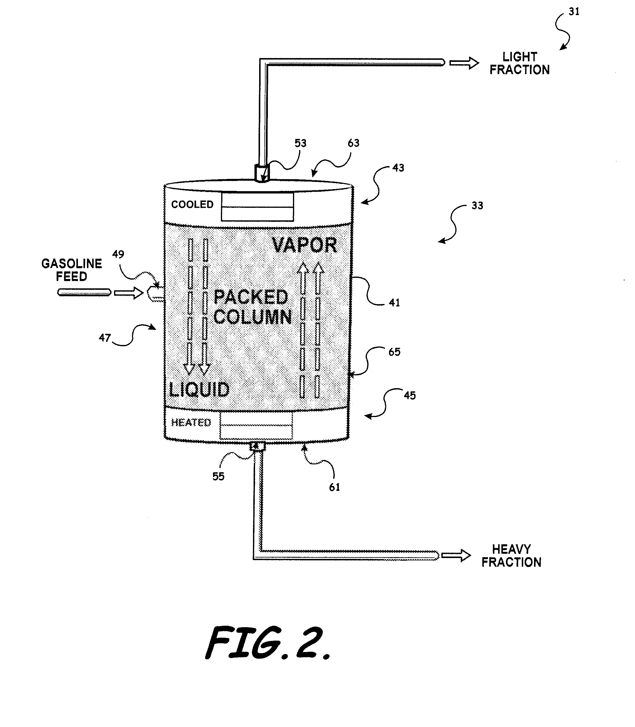
[0015]A vaporizing module is positioned adjacent the lower end portion of the housing to at least partially vaporize the feed fuel to enhance separation of the feed fuel into light fraction fuel and heavy fraction fuel components. A condensing module is positioned adjacent the upper end portion of the housing to condense heavy fraction fuel so that fuel exiting the light fraction output port is substantially light fraction fuel components by volume. A packed column including, for example, a three-dimensional column of
porous metal is positioned within the housing between the vaporizing module and the condensing module to enhance fuel distillation. The enhanced surface area provided by the
porous metal results in enhanced recirculation within the distillation column, improved concentration of the light end vapors at the top of the column, and improved concentration of heavy ends components at the bottom.
[0016]The controller provides control of the vaporization of the feed fuel by the vaporizing module and control of the condensation of the heavy ends or heavy fraction components by the condensing module responsive to various sensory inputs. The controller can ensure that the bottom of the distillation column is heated with a heating rate such that vapor generation occurs in the column at a desired
temperature and pressure, and can ensure that the top of the distillation column is cooled such that condensation occurs at a desired
temperature and pressure, resulting in the production of secondary fuel having the appropriate and desired characteristics.
[0017]The system can also include a
heat exchanger to preheat the distillation column feed fuel
stream and cool the hot heavy ends
stream exiting the distillation column bottom. The
heat exchanger beneficially can accomplish two major tasks. First, the
heat exchanger can help mitigate concerns about increasing evaporative emissions due to increase in main
fuel tank temperature by sending cooler fuel to the main
fuel tank. Second, the heat exchanger can help conserve energy that would otherwise need to be applied in the distillation column by recovering heat that would ordinarily be sent to the main fuel tank or elsewhere.
[0018]According to another embodiment of the present invention, provided is a fuel fractionating system for an engine having a fuel intake. The system can include a main fuel tank for supplying a primary feed fuel to the engine, and a distillation column
assembly to distill fuel to form a volatile light fraction secondary fuel from a portion of the primary feed fuel. The distillation column assembly can include a distillation column including a housing having an upper end portion, a lower end portion, and a medial portion extending therebetween, and a fuel feed port extending through the medial portion of the housing and positioned to receive feed fuel from the main fuel tank for distillation. A light fraction output port extends through the upper end portion of the housing and is positioned to allow output of distilled light fraction fuel. A heavy fraction output port extends through the lower end portion of the housing and is positioned to allow output of heavy fraction fuel. A vaporizing module is positioned adjacent the lower end portion of the housing to at least partially vaporize the feed fuel to separate the feed fuel into light fraction fuel and heavy fraction fuel components, and a condensing module is positioned adjacent the upper end portion of the housing to condense heavy fraction fuel components so that fuel exiting the light fraction output port is substantially light fraction fuel components by volume. The combination of the vaporizing module and condensing module synergistically results in the production of secondary fuel having the appropriate and desired characteristics.
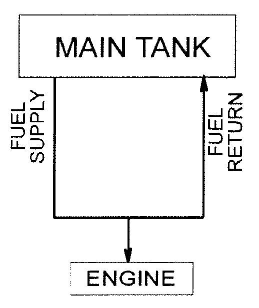
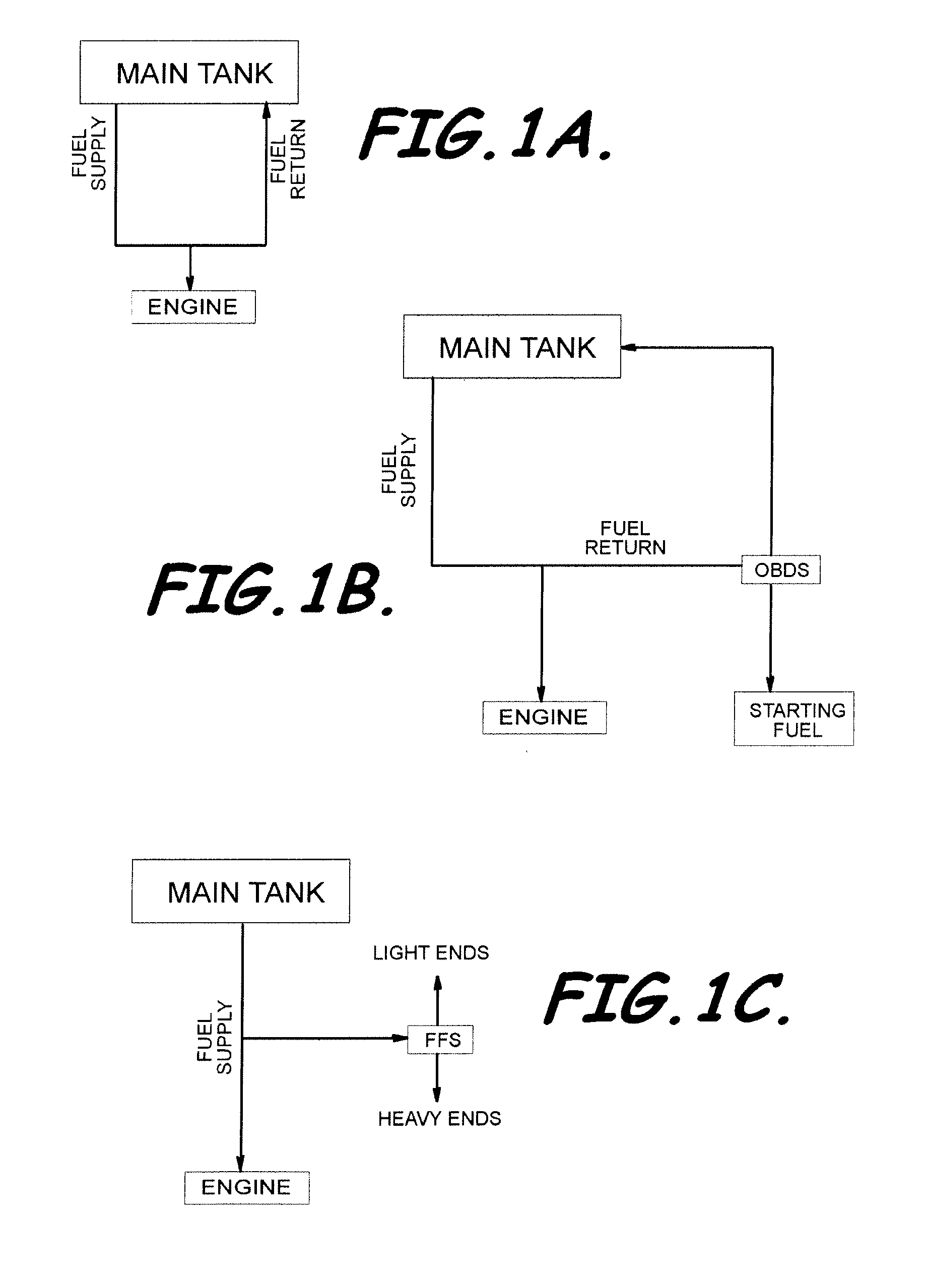
[0020]Beneficially, embodiments of the present invention provide the FFS and associated methods are an evolution of the OBDS, and thus, contain significant improvements over the OBDS in terms of performance,
usability and packaging, for example. Embodiments of an on-board FFS and methods to generate a starting fuel for
gasoline-powered engines, for example, beneficially provide (1) compact packaging, (2) more efficient, faster separation, (3) no need to wait for the engine to reach fully warmed
operating temperature, e.g., since a distillation column need not be heated by engine
coolant as typically with OBDS, and (4) bottoms liquid from FFS that can be consumed directly by the engine. Embodiments of the present invention can also beneficially eliminate or reduce the concern of higher evaporative emissions from returning warm fuel to main fuel tank, and can also beneficially enhance
engine power output through a combination of
ignition timing advance and consumption of high-
octane bottoms liquid. Beneficially, the FFS light fraction secondary fuel can be expected to feature at least five times the vaporization at moderate temperatures (21° C.-27° C.) than standard
gasoline, resulting in decreased
catalytic converter light-off times (at least 50%) and hydrocarbon emissions reductions on the order of 80-90% or more.

