Optical interference apparatus

a technology of optical interference and optical spectroscopy, applied in the field of optical interference apparatus, can solve problems such as optical interference, and achieve the effects of reducing the risk of optical interferen

Inactive Publication Date: 2007-08-23
SPECTRATECH
View PDF12 Cites 33 Cited by
  • Summary
  • Abstract
  • Description
  • Claims
  • Application Information

AI Technical Summary

Benefits of technology

[0025]In particular, when a medical doctor observes a region by use of a displayed image representing the profile, an image representing the biological information of a region corresponding to the region can be displayed while mixing (superimposing) the biological information image with the profile image. By virtue of this, a medical doctor can diagnose pathological condition and development considerably easily and accurately. Moreover, since blood volume, blood flow rate, change in blood flow, oxygen saturation, etc. can be easily calculated and displayed as biological information necessary for diagnosis of pathology, pathological condition and development can be diagnosed considerably easily and accurately. In addition, since the light emission section includes a plurality of light sources and can emit near infrared interferable light beams having different specific wavelengths, for calculation of biological information, the light emission section can selectively emit a near infrared interferable light beam having a suitable wavelength. This enables more accurate calculation of biological information, and assists a medical doctor's diagnosis more properly.
[0026]When the object to be examined is a living organism, the following effect can be achieved through simultaneous emission of a plurality of near infrared interferable light beams. That is, for example, when oxygen concentration within the artery or arteriole is calculated, the oxygen concentration must be calculated on the basis of the quantity of interference light stemming from a pulse wave of the blood flow. At this time, since the state of the pulse wave changes at extremely high speed, in the case where near infrared interferable light beams are successively emitted, the quantities of interference light rays detected by the light detection section for the near infrared interferable light beams represent different states of the pulse wave. Therefore, the calculated biological information may be of poor accuracy. In contrast, in the case where near infrared interferable light beams are simultaneously emitted, the quantities of interference light rays detected by the light detection section represent substantially the same state of the pulse wave. Therefore, the biological information can be calculated accurately, and a medical doctor's diagnosis can be assisted more properly.
[0027]Moreover, another feature of the present invention resides in that a light separation section for optically separating interference light rays produced as a result of optical interference at the light interference section is provided between the light interference section and the light detection section, and the light detection section includes a plurality of right-receiving means for receiving the interference light rays separated by the light separation section. By virtue of this configuration, even when near infrared interferable light beams having different specific wavelengths are simultaneously emitted from the light emission section, resultant interference light rays can be optically separated by the light separation section (e.g., a dichroic mirror or a half mirror). Therefore, the structure of the optical interference apparatus can be simplified.

Problems solved by technology

Thus, the greater portion of the light emitted from the light emission section causes optical interference.

Method used


Image

  • Optical interference apparatus
  • Optical interference apparatus
  • Optical interference apparatus

Examples


first embodiment

a. First Embodiment

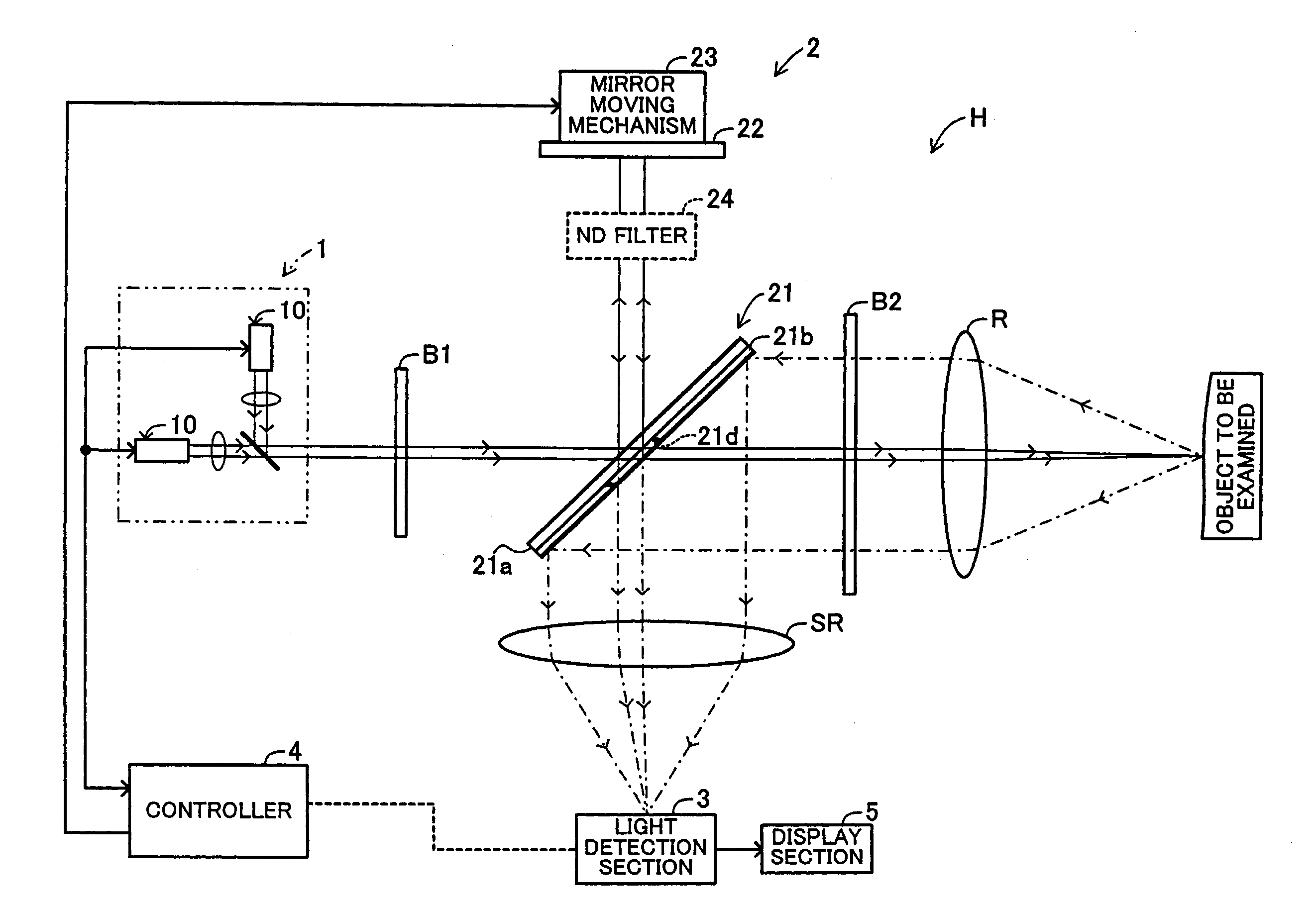
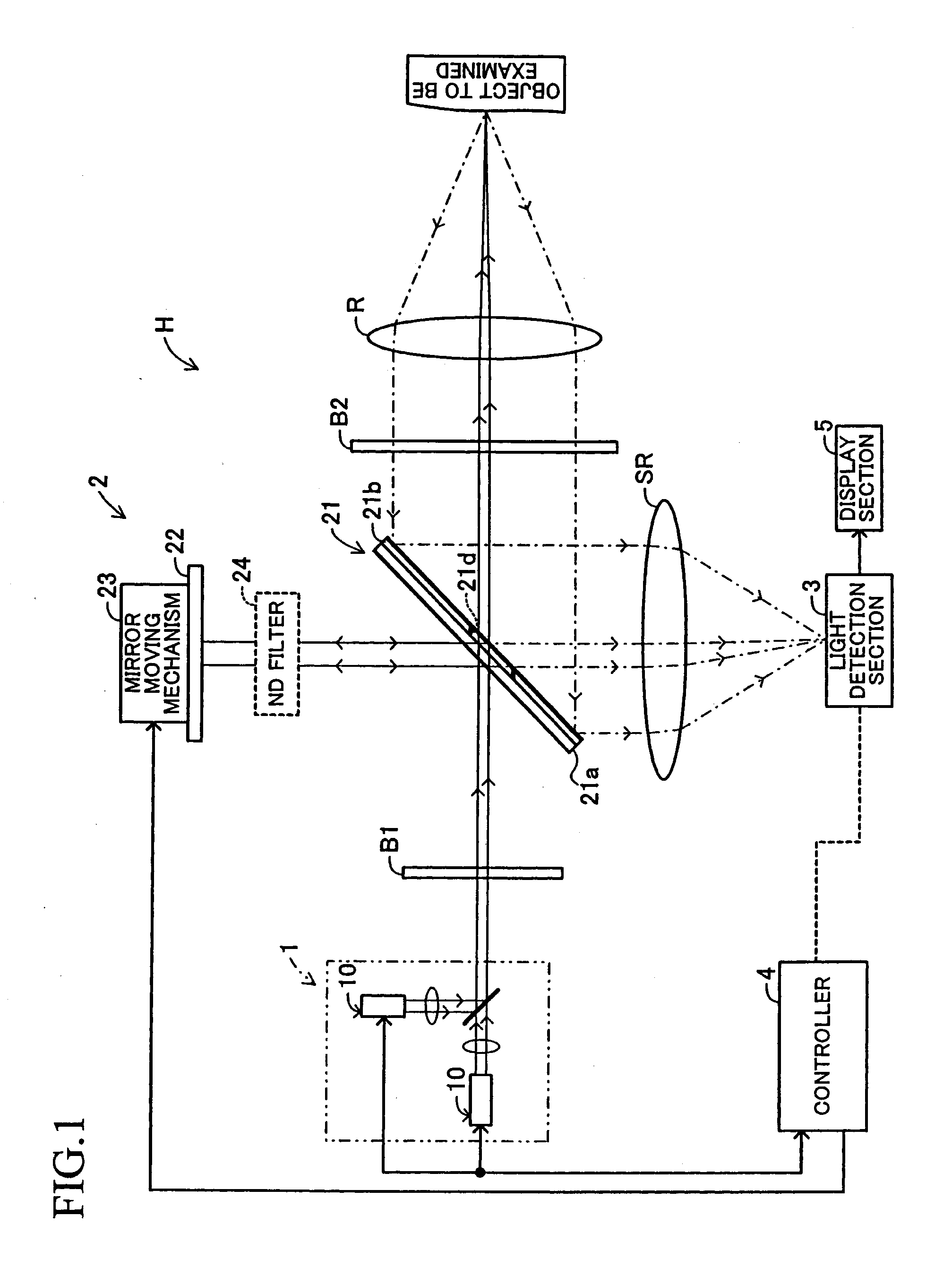
[0040]A first embodiment of the present invention will next be described with reference to the drawings. FIG. 1 schematically shows the configuration of an optical interference apparatus H according to the present embodiment. As shown in FIG. 1, the optical interference apparatus H includes a light emission section 1, a light interference section 2, and a light detection section 3. The optical interference apparatus H also includes a controller 4, which is mainly composed of a microcomputer including a CPU, ROM, RAM, etc.

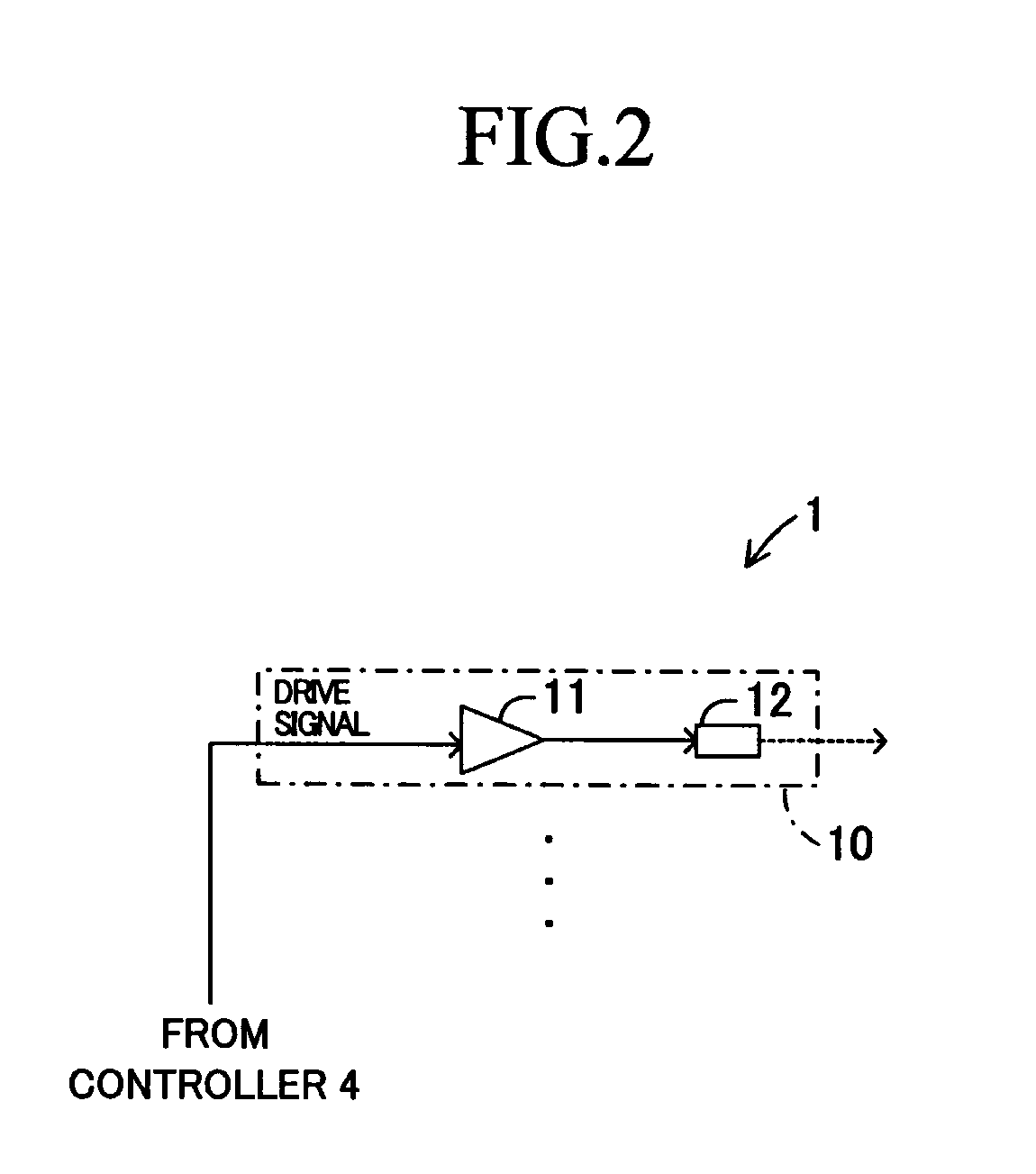
[0041]The light emission section 1 is composed of a plurality of light generators 10 which generate light beams having different specific wavelengths. In the present embodiment, as shown in FIG. 1, the light emission section 1 is composed of two light generators 10; that is, the light emission section 1 generates light beams having two specific wavelengths. However, no restriction is imposed on the number of the light generators 10 of the light em...

second embodiment

b. Second Embodiment

[0090]In the first embodiment, the controller 4 controls the light emission section 1 such that a predetermined, short interval is present between the light emission timings of the two light generators 10, and the light generators 10 emit near infrared interferable light in the form of pulses. The light emission timings can be made coincident with each other by means of spread-spectrum-modulation of the near infrared interferable light output from the light generators 10. Hereinafter, this second embodiment will be described, wherein portions identical with those of the first embodiment are denoted by the same reference numerals, and their detailed descriptions are not repeated.

[0091]The light emission section 1 of the optical interference apparatus H of the second embodiment outputs near infrared interferable light beams having specific wavelengths and having undergone spread-spectrum-modulation. Therefore, as shown in FIG. 9, each of the light generators 10 of ...


PUM


Abstract

A light emission section includes light generators which are operated on the basis of drive signals from a controller so as to emit near infrared interferable light beams having different specific wavelengths to a light interference section. The light interference section includes a beam splitter having a low-reflection region. The beam splitter allows a most portion of the near infrared interferable light beams to propagate toward an object to be examined, and reflects a portion of the near infrared interferable light beams to a movable mirror. The beam splitter causes interference between measurement light reflected by the object and reference light reflected by the movable mirror, and the resultant interference light propagates to a light detection section. The light detection section receives the interference light and calculates predetermined information regarding the object by making use of the quantity distribution of the interference light. A display section displays the calculated information.

Description

BACKGROUND OF THE INVENTION[0001]1. Field of the Invention[0002]The present invention relates to an optical interference apparatus which obtains, in a non-contacting manner, information regarding an object to be examined by making use of optical interference.[0003]2. Description of the Related Art[0004]Conventionally, optical interference phenomena have been widely utilized for measuring a very small change in distance between objects, the surface shape of an object, or the like. Of various apparatuses utilizing optical interference phenomena, measurement apparatus utilizing a Michelson interferometer, which can readily produce an optical interference phenomenon, are widely known. The Michelson interferometer includes a half mirror or beam splitter which optically splits a light beam into two light beams propagating in two directions. A light beam emitted from a light source is optically split into two light beams by means of the beam splitter disposed on the optical path of the emi...

Claims


Application Information

Patent Timeline
Patent Type & Authority Applications(United States)
IPC IPC(8): G01B11/02
CPCA61B5/0059G01N21/4795A61B5/14551
Inventor OHASHI, MITSUOITO, YOSHITOSHI
Owner SPECTRATECH
Why Eureka
Try Eureka