Sensor-less control method for linear compressors

a linear compressor and sensorless control technology, applied in the direction of motor/generator/converter stopper, dynamo-electric converter control, pump parameter, etc., can solve the problems of system drawbacks, inability to maintain constant top dead volume, phase delay between current pulse and piston position, etc., to achieve the effect of maximum compression ratio and maximum compression ratio

Active Publication Date: 2007-08-23
INFINEON TECH AMERICAS CORP
View PDF20 Cites 72 Cited by
  • Summary
  • Abstract
  • Description
  • Claims
  • Application Information

AI Technical Summary

Benefits of technology

[0049]It is therefore an object of the present invention to provide an improved control method in which the coil's current includes all the information about the mechanical system and the load spring effect.
[0050]It is another object of the present invention to provide a control method which allow the piston position to be precisely controlled to reach the near zero TDC when maximum compression ratio is desired, and to achieve any piston position relative to the top dead point in case compression ratio lower than the maximum is needed.
[0051]It is a further object of the present invention to allow the mechanical structure to be designed to work with any resonance frequency, thus allowing optimization of the mechanical structure itself.
[0052]Provided is a method of protecting a cylinder of a compressor comprising a piston, a linear permanent magnet (PM) having a coil and a magnet, and a sensor-less control of the PM for moving the piston in and out of the cylinder, the cylinder havin

Problems solved by technology

U.S. Pat. No. 5,947,693 describes using a position sensor but due to the frequency response of the mechanical system, there exist a phase delay between the current pulse and the piston position (Sp).
However, the load changes the initial piston position, thus making constant top dead volume not possible.
Such system has drawbacks due to the errors introduced in the stroke amplitude reading.
This kind of unstable operation depends on suction and discharge pressure and, ultimately, on outside air temperature.
The control algorithm is a bit more complex, because instabili

Method used


Image

  • Sensor-less control method for linear compressors
  • Sensor-less control method for linear compressors
  • Sensor-less control method for linear compressors

Examples


Embodiment Construction

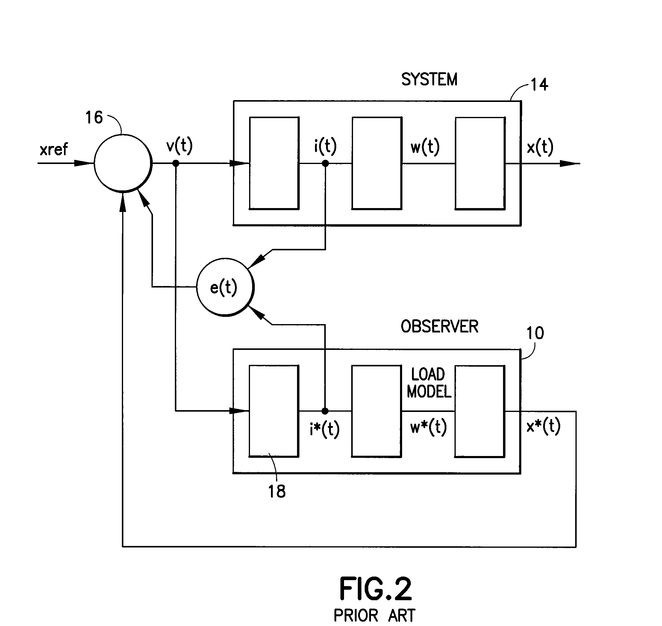
[0058]A generalized Luenberger observer control structure 10 for controlling a linear compressor 14 is illustrated in FIG. 2. A simplification of the structure 10 can be recognized in most of the prior art references. Without a position sensor, the only observable parameter in the structure 10 is the current i*(t). The current error, in its various forms, is used to correct an estimation of a of a piston position coming from the observer block 10.

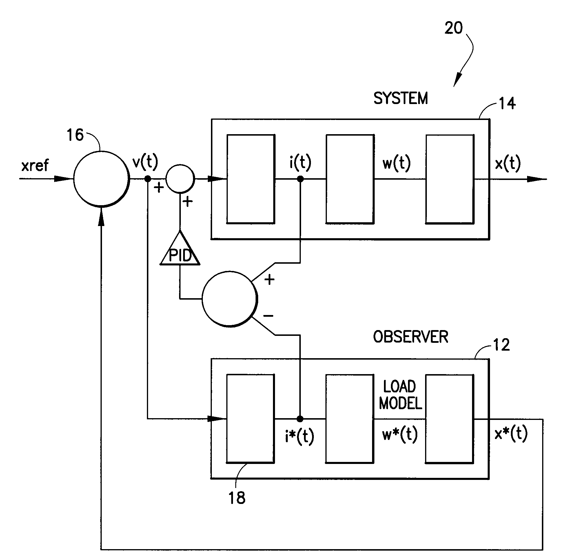
[0059]FIG. 3 illustrates a control structure 20 of one embodiment of the present invention. High frequency components of an error between an actual current i(t) from the linear compressor system block 14 and a current i*(t) in the system model or the observer block 12 include all information about the linear compressor system 14 that is to be controlled.

[0060]The observer block 12 is a model of a motor and of a mechanical system. It may be advantageously implemented by iMotion digital control hardware structure, which is characterized by ex...


PUM


Abstract

A method of protecting a cylinder of a compressor comprising a piston, a linear permanent magnet (PM) having a coil and a magnet, and a sensor-less control of the PM for moving the piston in and out of the cylinder. The method including the steps of receiving a reference position of the piston from a temperature control loop; deriving a compensation voltage and a load spring effect information from a current through the coil; providing a model input voltage to a model of a mechanical structure of the compressor for predicting position of the piston, the model input voltage comprising a first voltage derived from the reference position; a compressor input voltage comprising the first voltage and the compensation voltage; and using a position control loop to recognize when the maximum compression ratio is desired and controlling the piston to achieve maximum compression ratio without causing damage to the discharge valve.

Description

CROSS-REFERENCE TO RELATED APPLICATION[0001]This application is based on and claims priority to U.S. Provisional Patent Application Ser. No. 60 / 775,283, filed on Feb. 21, 2006 and entitled AN IMPROVED SENSOR-LESS CONTROL METHOD FOR LINEAR COMPRESSORS, the entire contents of which are hereby incorporated by reference herein.BACKGROUND OF THE INVENTION[0002]The present invention relates to linear compressors and more particularly to an improved method for sensor-less control of the linear compressors.[0003]In the past six to seven years, linear compressors have gained increased popularity due to simplifications in their mechanical structure, ease of use when driven at both fixed and variable capacity, and higher efficiency.[0004]Linear permanent magnet (PM) machines are very simple. They are formed from a fixed coil and a moving magnet or, vice-versa, a fixed magnet and a moving coil. Such linear PM machines are well known in the audio field as the basic voice coil actuator for loudsp...

Claims


Application Information

Patent Timeline
IPC IPC(8): F04B49/06
CPCF04B35/045F04B2203/0402F04B2201/0201F04B49/065
Inventor BOCCHIOLA, CESARE
Owner INFINEON TECH AMERICAS CORP
Why Eureka
Try Eureka