
Cuff member

a cuff and rib technology, applied in the field of cuff members, can solve the problems of reduced adhesion between the cuff members, increased infection, and cuff members, and achieve the effects of preventing exposure, inhibiting downgrowth, and enhancing cell invasion and engrafting

Inactive Publication Date: 2007-08-23
NAT CEREBRAL & CARDIOVASCULAR CENT +1
View PDF5 Cites 6 Cited by
  • Summary
  • Abstract
  • Description
  • Claims
  • Application Information

AI Technical Summary

Benefits of technology

[0010] The present invention was achieved in view of such problems of the related art. Accordingly, it is an object of the present invention to provide a cuff member unit that can prevent exposure due to the downgrowth and a cuff member for use in the cuff member unit. In particular, it is an object of the present invention to provide a cuff member that enhances the invasion and engraftment of cells from subcutaneous tissue of a living body and robustly adheres to the subcutaneous tissue through the vascularization of capillary vessels, and can consequently inhibit the downgrowth and reduce infection problems including tunnel infection. This cuff member can improve the isolation of subcutaneous tissue from the outside in the ventricular assist device therapy. Thus, a patient can take a shower.
[0013] Since the cuff members according to the first aspect and the second aspect have a three-dimensional network open-cell porous structure having the specific average pore size and the specific apparent density and formed of a thermoplastic resin or a thermosetting resin, the cuff members enhance the invasion and engraftment of cells into pores of the three-dimensional network open-cell porous structure and thereby can robustly adhere to body tissue.
[0014] The cuff members according to the first aspect and the second aspect enhance the invasion and engraftment of cells from subcutaneous tissue of a living body. Thus, the cuff members can robustly adhere to the subcutaneous tissue through the vascularization of capillary vessels. Consequently, the cuff members isolate a wound from the outside, block exacerbating factors such as bacterial infection during healing, inhibit the downgrowth, and reduce infection problems including tunnel infection.
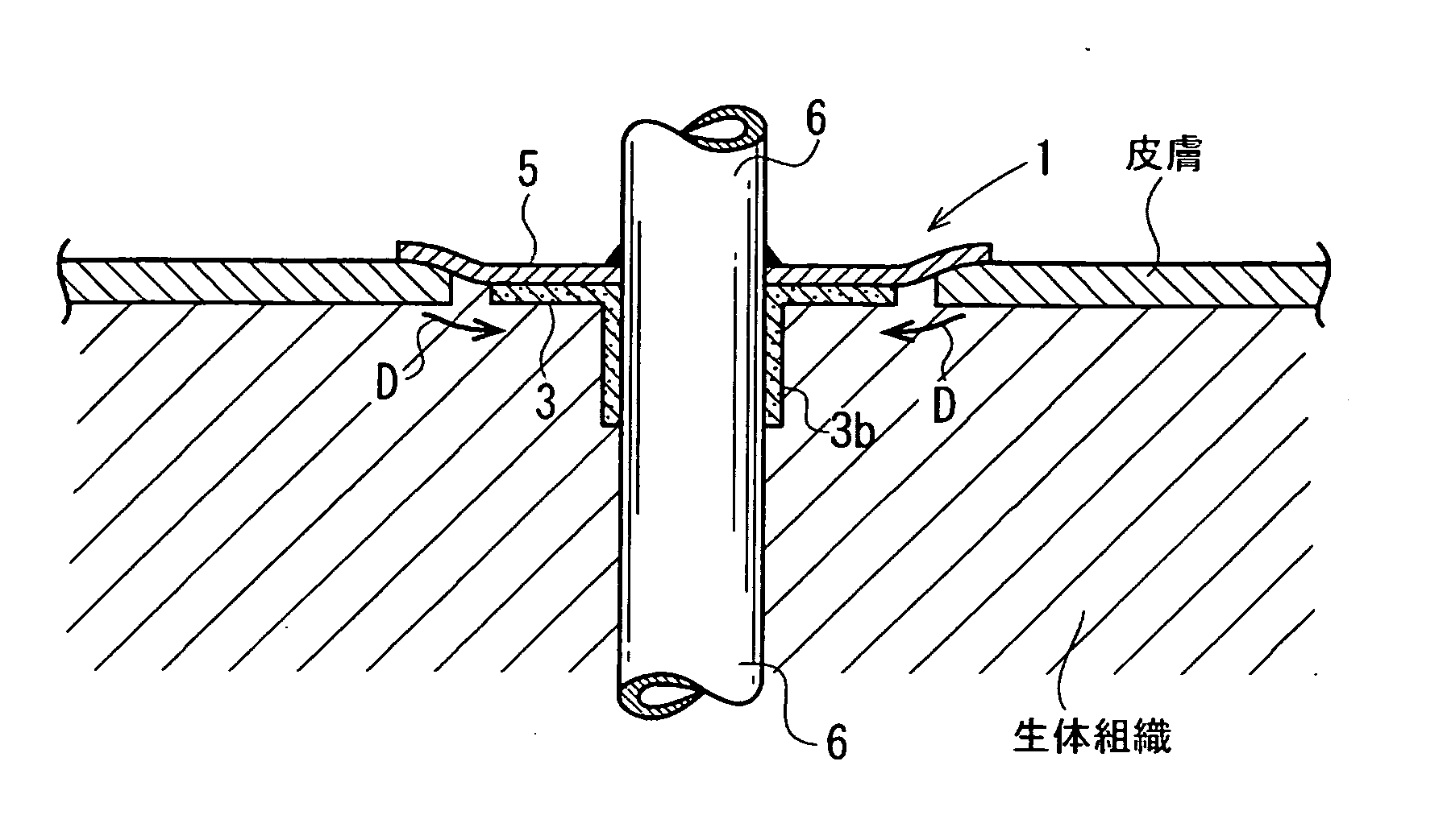
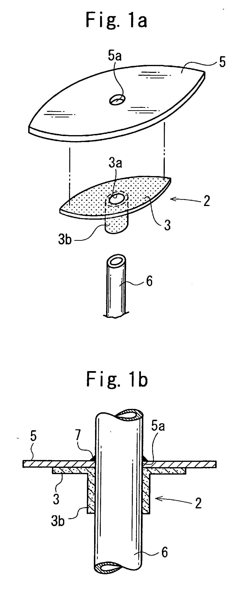
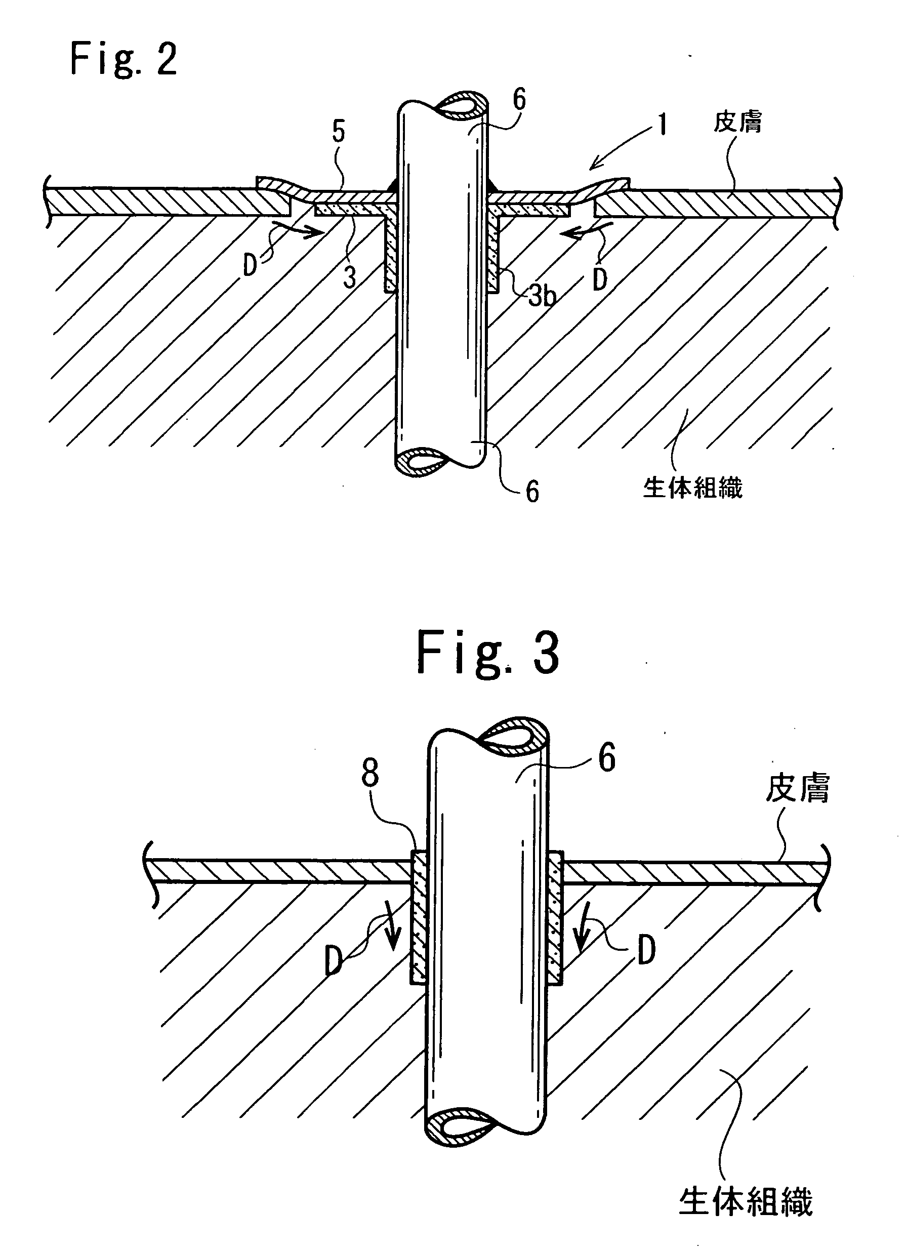
[0016] In a cuff member using the cuff member according to the first aspect, a flange is covered with a pad, and the pad extends beyond the flange. Thus, it takes time for the downgrowth of skin to affect the tubular portion. In addition, such a structure can prevent water from entering subcutaneous tissue along a cannula.
[0017] In the cuff member according to the second aspect, the first flange covered with the polymer resin pad retards the downgrowth from affecting the tubular portion. In addition, such a structure can prevent liquid from entering subcutaneous tissue along a cannula. The first flange is placed under skin and is organized through invasion of subcutaneous tissue. The end of epidermis overlying the first flange is bonded to the edge of the second flange. Thus, implantation can be performed without the epidermis growing over the polymer resin pad. Epidermis is inhibited from growing under the polymer resin pad for a long period of time.
[0018] Consequently, the cuff member unit can be implanted in a living body for a long period of time without the effects of the downgrowth. A patient who receives the ventricular assist device therapy can take a shower without wetting an insertion cannula.

Problems solved by technology

A typical trouble for which reduced adhesion between the cuff member and the subcutaneous tissue caused by the stress loading is concluded to be responsible is an infection problem such as tunnel infection.
In cases of ventricular assist device therapy, such an infection problem is experienced more frequently.
Peritoneal dialysis, in which a catheter is inserted under the skin and is placed for a long period of time, also has a momentous issue concerning the cuff member.
Thus, subcutaneous tissue and the catheter insufficiently adhere to each other.
This downgrowth pocket makes the access of an antiseptic solution difficult, is responsible for epidermal inflammation and tunnel infection, and eventually induces peritonitis.
Thus, it is difficult to grow the subcutaneous tissue at the catheter insertion point.
Consequently, the cuff member cannot inhibit the downgrowth.
However, in such a cuff material, while the porous material may be infiltrated with subcutaneous tissue and be organized, epidermis cannot be bonded to the porous material and grows under the subcutaneous tissue along the insert tube.
Consequently, the downgrowth cannot be inhibited.
However, epidermis cannot be bonded to the discoidal porous material and grows along a catheter outside the body.
Pus or a residue of an antiseptic solution may be accumulated in the gap and induce pocket infection.
In addition to the downgrowth, the ventricular assist device therapy has another momentous issue.
Since subcutaneous tissue is insufficiently isolated from the outside at a cannula insertion point, the insertion point must not be dipped into water.
This considerably decreases patient's quality of life (QOL).

Method used


Image

  • Cuff member
  • Cuff member
  • Cuff member

Examples


example 1

[0103] A thermoplastic polyurethane resin (Nippon Miractran Co., Ltd., Miractran E980PNAT) was dissolved in N-methyl-2-pyrrolidinone (Kanto Chemical Co., Inc., reagent for peptide synthesis, NMP) at room temperature with a dissolver (about 2,000 rpm) to yield 12.5% solution (weight / weight). About 1.0 kg of the NMP solution was charged into a planetary mill (Inoue Manufacturing Co., Ltd., capacity of 2.0 L, PLM-2). Methylcellulose (Kanto Chemical Co., Inc., reagent, 50 cp grade) the amount of which corresponds to half the weight of the polyurethane resin was added to the NMP solution and was stirred at 60° C. for 120 min. The solution was continuously stirred and was degassed under vacuum at 20 mmHg (2.7 kPa) for 10 min to yield a polymer dope.

[0104] Two 150 mm×150 mm square Teflon frames having a thickness of 3 mm and an opening of 140 mm×140 mm were stacked and were fixed with a square filter paper for a chemical experiment (Toyo Roshi Kaisha, Ltd., for quantitative analysis, No. ...

example 2

[0120] Example 2 according to the second aspect will be described below.

[0121] A polymer dope was prepared as in Example 1.

[0122] Two 150 mm×150 mm square fluorocarbon resin frames having a thickness of 5 mm and an opening of 140 mm×140 mm were stacked and were fixed with a square filter paper for a chemical experiment (Toyo Roshi Kaisha, Ltd., for quantitative analysis, No. 2) having a size of 150 mm×150 mm interposed therebetween. The polymer dope was poured into the frame. An excessive amount of polymer dope was removed with a glass rod. Then, a 150 mm×150 mm square filter paper for a chemical experiment (Toyo Roshi Kaisha, Ltd., for quantitative analysis, No. 2) was placed on the frame unit and was fixed. The frame unit was immersed in methanol under reflux for 72 hours to extract and remove NMP from the filter papers for a chemical experiment disposed on both sides of the frame unit and thereby solidify the polyurethane resin. Methanol was continuously refluxed and was replac...


PUM


Abstract

A cuff member that enhances the invasion and engraftment of cells from subcutaneous tissue of a living body and robustly adheres to the subcutaneous tissue through the vascularization of capillary vessels, and can consequently isolate a wound from the outside, block exacerbating factors such as bacterial infection during healing, inhibit the downgrowth, and reduce infection problems including tunnel infection. A cuff member 2 includes a flange 3 and a tubular portion 4. The cuff member 2 includes a three-dimensional network open-cell porous structure, which is formed of a thermoplastic resin or a thermosetting resin and has an average pore size of 100 to 1000 μm and an apparent density of 0.01 to 0.5 g / cm3. A pad 5 overlies the flange 3. A tube 6 passes through the pad 5 and the flange 3.

Description

CROSS REFERENCE TO RELATED APPLICATION [0001] This is a continuation application of PCT / JP2005 / 003775 filed on Mar. 4, 2005.FIELD OF THE INVENTION [0002] The present invention relates to a cuff member that can be invaded by cells generated from body tissue and can robustly adhere to body tissue, and more particularly to a cuff member useful at an insertion point in a biological skin in therapy in which a cannula or a catheter is subcutaneously inserted, such as blood circulation using a ventricular assist device, peritoneal dialysis, intravenous hyperalimentation, gastrogavage, cannula DDS, and catheter DDS. BACKGROUND OF THE INVENTION [0003] Unlike a urethral catheter, gastrointestinal hyperalimentation, and airway management, in which a cannula or a catheter is placed in a vessel opened outside, in recently developed therapy, such as a ventricular assist device or a peritoneal dialysis, a subcutaneous tissue must be incised and a cannula or a catheter must be placed in a living bo...

Claims


Application Information

Patent Timeline
IPC IPC(8): A61B17/00A61L31/00A61L31/14A61M25/02A61M25/04
CPCA61L31/146A61M2025/0266A61M25/04A61M25/02A61M2025/0293
Inventor TATSUMI, EISUKEMIZUNO, TOSHIHIDETAENAKA, YOSHIYUKINEMOTO, YASUSHIOKAMOTO, YOSHIHIROTAZAWA, HARE
Owner NAT CEREBRAL & CARDIOVASCULAR CENT
Learn More