Control system of floating mobile body

a control system and floating technology, applied in the direction of electric programme control, program control, instruments, etc., can solve the problem of low response speed to disturbances, adverse effects on control performance, and so on, and achieve the effect of suppressing nonlinearity of effector dynamic characteristics, preventing adverse effects on control performance, and not increasing the influence of sensing delay

Active Publication Date: 2007-08-30
MAN MACHINE SYNERGY EFFECTORS INC
View PDF1 Cites 62 Cited by
  • Summary
  • Abstract
  • Description
  • Claims
  • Application Information

AI Technical Summary

Benefits of technology

[0078] Conventionally, a thrust of a thruster is controlled by feeding back a sensor information concerning the position / velocity of a floating mobile object, while the present invention directly feeds back a generated thrust to control a thrust of an effector, thereby realizing a high-speed response according to a principle. Thus, the above-mentioned sensing delay problem is alleviated. Particularly, when the thrust force transfer gate is provided as hardware (see, for example, the first and second instances of the first embodiment), the influence of sensing delay is not increased even if the mass of the floating mobile object is large or the thrust of the effector is low.
[0079] In a floating mobile object control system of the present invention, the thrust of the effector is controlled by a thrust control part feeding back a thrust at the thrust transfer gate as described below. This realizes the above-mentioned high-speed response. At the same time, by applying to the thrust control part an existing control technique (e.g., sliding mode control), which offers robustness to nonlinearities, it is possible to suppress a nonlinearity of an effector dynamic characteristic, thereby preventing adverse influence on control performance. Conventionally, linearization of the effector dynamic characteristic is performed by feedforward compensation based on a dynamic characteristic model of the effector, however, it is significantly time-consuming and imposes a heavy computation load. The floating mobile object control system of the present invention realizes the linearization by thrust feedback, which does not necessarily use the dynamic characteristic model, and therefore it is possible to construct a control system with less computation load.
[0080] In addition, in the conventional art, an unignorable delay in time occurs during a period of time since sensing is carried out as described above until a thrust command is actually fed to the thruster, and as a result, in order to keep the floating mobile object on a predetermined trajectory, it is inevitable, in most cases, to drive the floating mobile object more than necessary, for example, because it is required to repeatedly correct an overshoot and an undershoot a considerable number of times. The task of suitably performing gain tuning of the control system is extremely significant and requires experience in addition to labor and time.
[0081] On the other hand, according to the present invention, it is possible to feed a thrust that is actually required by the thruster in a timely manner, and therefore it is possible to avoid driving the thruster and the floating mobile object more than necessary. In addition, the floating mobile object is not caused to consume thruster drive energy more than necessary, whereby it is possible to achieve an effect of reducing energy consumption of the floating mobile object.
[0082] Also, in the floating mobile object control system of the present invention, influence of unknown disturbances can be immediately sensed as thrust error at the thrust transfer gate, and compensated for by local feedback control of the thrust control part, and therefore levels above the thrust planning part are not required to take the disturbances into consideration. Specifically, by only requiring the thrust planning part to issue a command such as “stand still” or “go straight”, it is possible to automatically compensate for the influence of the disturbances in the thrust control part, thereby realizing a desired operation that is previously planned. Also, it is possible to realize a high-speed response compared to a conventional case where the influence of the disturbances is sensed by position / velocity error.
[0083] On the other hand, according to a floating mobile object acceleration sensing system of the present invention, an estimated acceleration value for the main body part can be obtained by using a previously identified inertia matrix of the main body part, an output from the force / torque sensor from the thrust transfer gate, and, if necessary, an output from the inclination angle sensor of the main body part, and therefore it is possible to sense an acceleration of the floating mobile object with high precision to such an extent that a minor change in acceleration can be sensed, regardless of size and weight of the floating mobile object or without depending on the capability of the acceleration sensor, and also possible to, when guiding the floating mobile object by inertial navigation, accurately guide the floating mobile object onto a desired trajectory.

Problems solved by technology

As such, in the conventional control of a floating mobile object, information concerning the position and velocity of a floating mobile object, which is a subject of control, is fed back to directly handle a thrust command to an effector, and in the case of a floating mobile object generally having an effector with a relatively slow response speed, it takes a time while after the command is sent to the effector, the effect of which is reflected in the position and velocity of the floating mobile object, until the sensor obtains them, therefore there arises a problem where control performance is adversely affected (which is what is called a sensing delay problem).
Further, a floating mobile object in a stream of water or air is always affected by hydrodynamic disturbances such as waves and tidal current or wind, and in addition, as shown in FIG. 11, the floating mobile object 10 in water is connected with an umbilical cable C (a feeder, a communication line or the like) from above the water, which often pulls the floating mobile object 10, therefore in the case of the above-described control technique, a response to unknown disturbances takes time, causing a problem where control performance is adversely affected.
Specifically, the prior known control technique operates activates the thrusters T after the floating mobile object 10 is moved by the reaction force and torque of the robot arm A, and therefore the so-called sensing delay problem where a response speed to disturbances is low still remains unsolved.
In the case where there are a plurality of robot arms A, the dynamics become more significantly complicated.
Arithmetic of such control system is considerably time-consuming, and imposes a heavy computation load on the computer.
Therefore, it is practically very difficult to configure the above-described control system with a small computer.
(2) Also, the above-described control system requires a number of dynamic parameters such as the mass, moment of inertia and gravitational center position of each link of the robot arm A and the main body, and proper control cannot be realized by using these dynamic parameters unless their values are all correct.
Thus, it is required to have a database of objects that can be held or measure dynamic characteristics of the object, therefore there arises a problem where the use is practically limited.
(3) Further, a floating mobile object in a stream of water or air is always affected by unknown hydrodynamic disturbances such as waves and tidal current or wind, and in addition, as shown in FIG. 11, the floating mobile object 10 in water is connected with an umbilical cable C (a feeder, a communication line or the like) from above the water, which often pulls the floating mobile object 10, besides it is not possible to model the unknown disturbances, and in addition it is difficult to predict influence of the disturbances, therefore such a model-based control technique is disadvantageous in that it cannot be fundamentally adapted to control of a floating mobile object.
Also, the thrusters used as effectors for controlling the position / velocity of the floating mobile object generates a thrust by taking advantage of a stream, and therefore a high nonlinearity caused by the stream is present between an input command to the thrusters and a thrust that is actually outputted.
Such a nonlinearity results from various factors, and conventionally it is difficult to perform control with consideration of all of them (a problem of what is called a nonlinearity of an effector dynamic characteristic).
While both of the above-described control techniques according to Patent Document 1 and Non-Patent Document 1 measure and feed back force partially, they do not cancel influence of waves and tidal current or wind which are the greatest disturbances to the floating mobile object.
On the other hand, aside from the above-described problems, there is a below-described problem with inertial navigation, which is a prior known technique widely used for navigating a floating mobile object.
Specifically, the inertial navigation uses an acceleration obtained from a floating mobile object, and in the case where the floating mobile object itself is large and heavy, a prior known acceleration sensor, which temporally converts an acceleration to a displacement and outputs the value of acceleration as an electric signal, is structurally unable to sense a minor change in the acceleration with high precision, therefore there arises a problem where a noticeable error is present between the acceleration value obtained from the sensor and an actual acceleration value.
Such an error between the acceleration values considerably affects the accuracy of the inertial navigation itself, causing inconvenience of being unable to accurately guide the floating mobile object onto a desired trajectory.

Method used


Image

  • Control system of floating mobile body
  • Control system of floating mobile body
  • Control system of floating mobile body

Examples


first embodiment

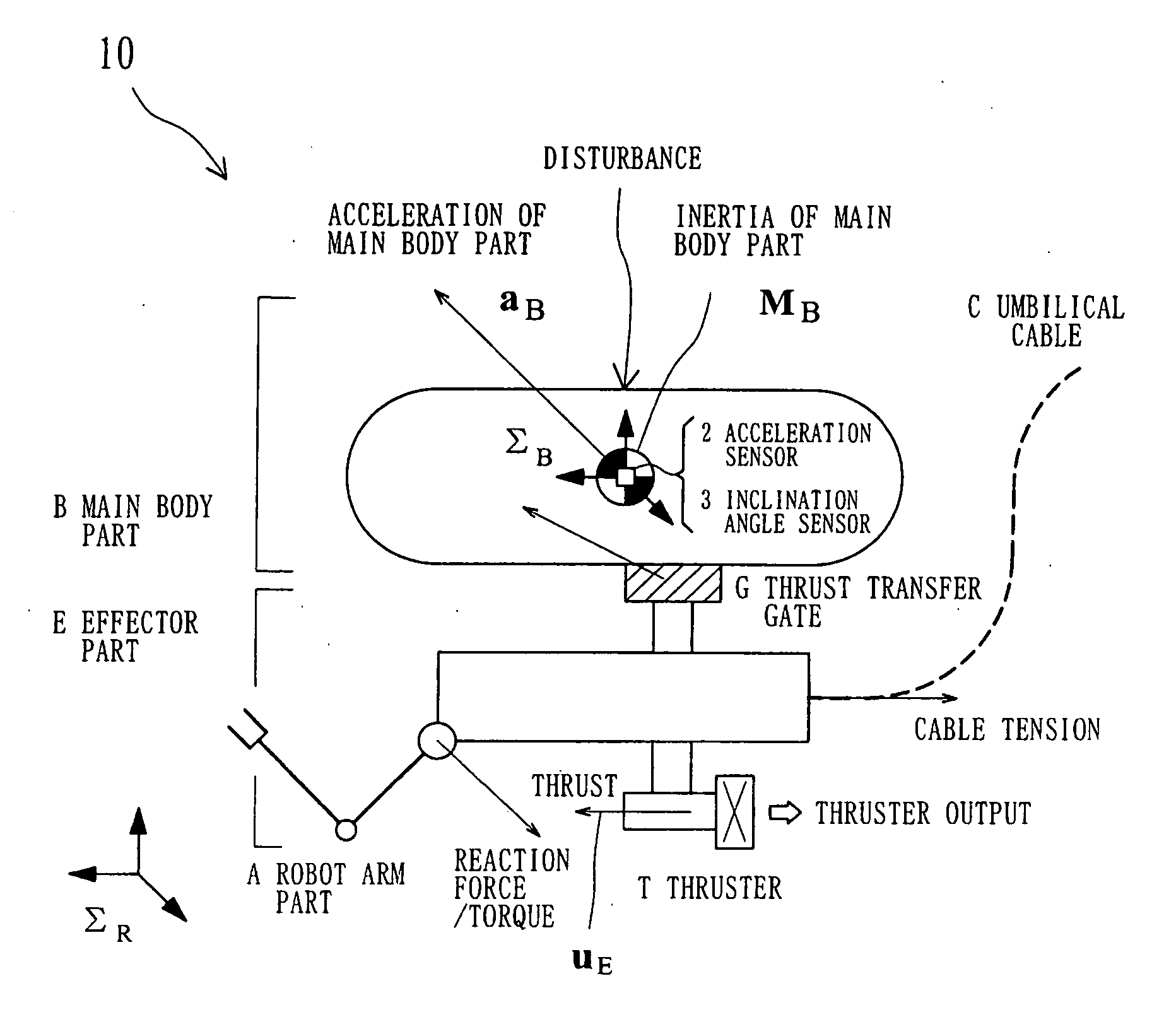
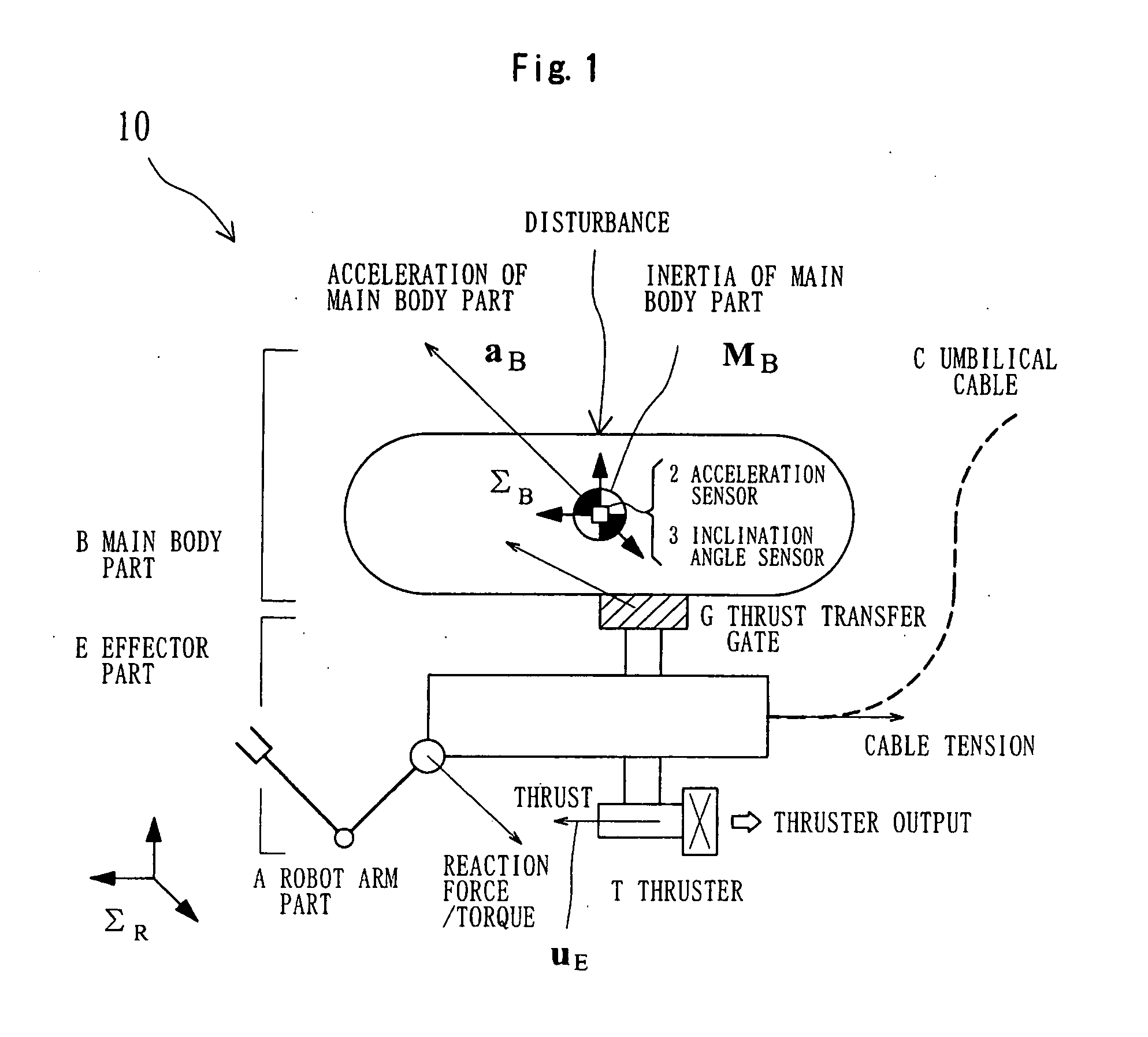
[0137] Hereinafter, an embodiment of the present invention and the action thereof will be described with reference to FIGS. 1 through 7 in relation to an underwater robot, which typifies a target for which the present invention is carried out. The underwater robot is nothing less than a floating mobile object for floating in three-dimensional space, and in the case of applying a control system of the present invention to the underwater robot, it is necessary to compensate for influence of a gravitational acceleration, therefore it is required to provide inclination angle measurement means capable of measuring an inclination of a main body part as defined by the invention according to (7) above. The same can be said of the invention according to (5) above to which the notion of a virtual thrust transfer gate system is applied, and in the case of applying a control system of the present invention, which employs the notion of the virtual thrust transfer gate system, to a floating mobil...

second embodiment

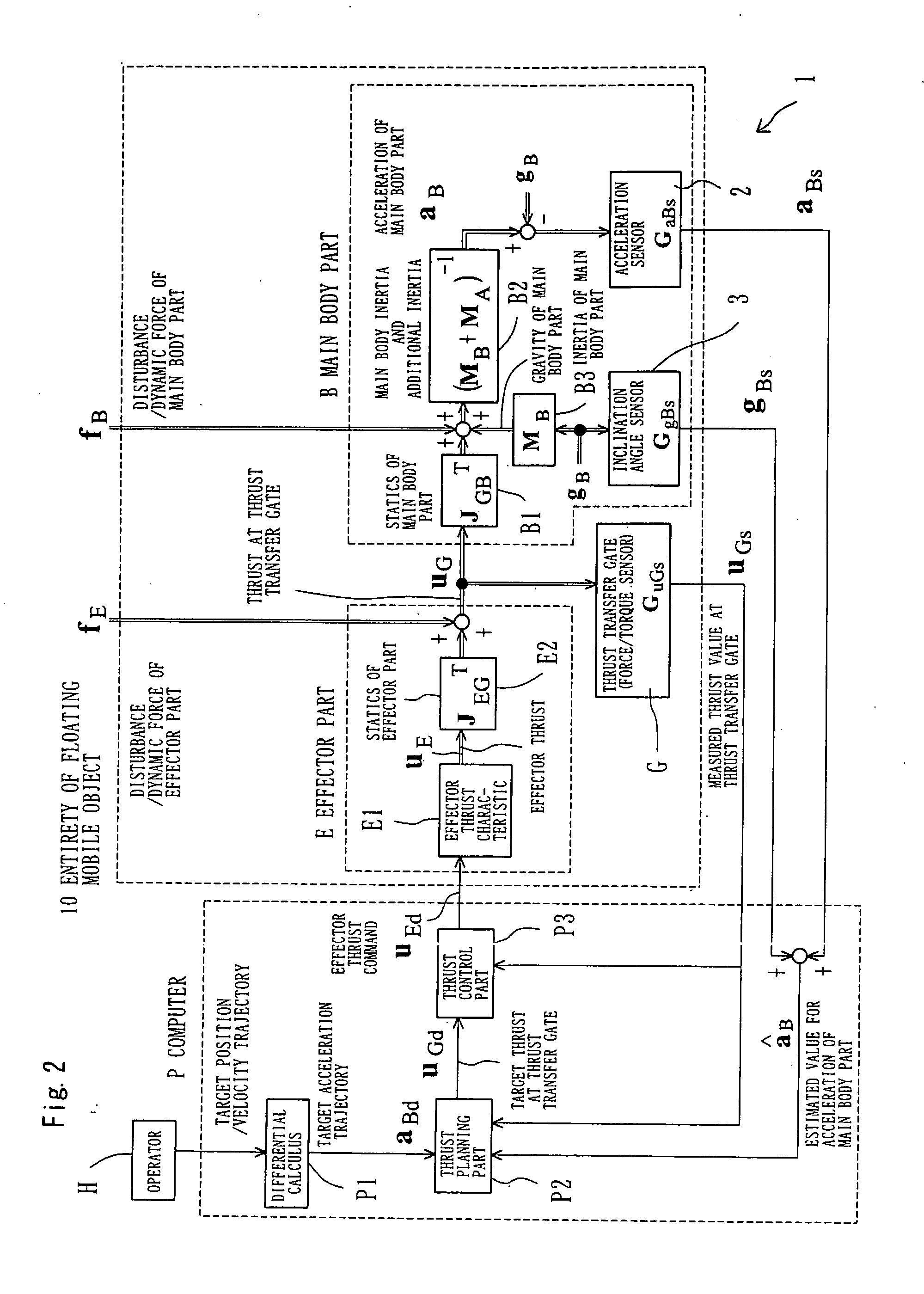
[0245] Described next is an embodiment of a floating mobile object acceleration sensing system of the present invention. As in the first embodiment, the present embodiment is described in relation to an underwater robot as an application target. Note that the underwater robot is nothing less than a floating mobile object for floating in three-dimensional space, and in the case of applying an acceleration sensing system of the present invention to the underwater robot, it is necessary to compensate for influence of a gravitational acceleration as in the first embodiment, therefore it is required to provide inclination angle measurement means capable of measuring an inclination of a main body part.

[0246] In the present embodiment, a thrust transfer gate is used for estimating an acceleration of the main body part. The acceleration sensing system according to the present embodiment is configured as shown in FIGS. 3 and 7. FIG. 3 is a schematic diagram of a floating mobile object, and ...

example 1

[0262] As described in the above first embodiment section, the floating mobile object control system of the present invention performs thrust control, and therefore, to be strict, an acceleration trajectory, rather than a position / velocity trajectory, is realized. Here, it is not possible to avoid influence of drift caused by integration error in acceleration, and therefore the motion on which the present invention solely exhibits a remarkable effect is that in a relatively high frequency range. As for low-frequency slow motion, it is necessary to additionally use a conventional control technique for feeding back a position / velocity, but in such a case also, it is possible to improve precision compared to the case of using the conventional technique alone.

[0263] Hereinbelow, an example of the present invention is described in relation to a control system employing conventional position / velocity feedback control in addition to each instance of the floating mobile object control syst...


PUM


Abstract

An object of the invention is to provide a floating mobile object control system capable of causing a floating mobile object to stand still in a predetermined position with high precision or track a target trajectory with high precision, even under disturbances caused by waves, tidal current, etc. A floating mobile object control system of the present invention capable of achieving the above object is a control system 1 for a floating mobile object 10, in which the floating mobile object includes: a main body part B that can be considered as a single rigid body constituting a part of the floating mobile object; an effector part E for generating a thrust for the floating mobile object; and a thrust transfer gate G for dynamically connecting the main body part and the effector part, the thrust transfer gate being adapted to be able to actually measure a thrust from the effector part acting on the main body part, and a measured value for the thrust from the thrust transfer gate G is used to obtain a thrust command to the effector part E (FIG. 4).

Description

TECHNICAL FIELD [0001] The present invention relates to control systems for floating mobile objects in water, air, outer space, etc., or mobile objects for sliding on a plane. BACKGROUND ART [0002] First, a prior known floating mobile object control technique is described with reference to FIGS. 11 through 14 and so on. FIG. 11 is a schematic diagram of a prior known floating mobile object, and FIGS. 11 through 14 are schematic diagrams illustrating a prior known floating mobile object control technique. [0003] As shown in FIG. 11, in order to control the position and velocity of the main body of a floating mobile object 10 such as an underwater robot, the main body is provided with a sensor 13 by which the position and velocity of the main body of the floating mobile object 10 are sensed and fed to a subtraction circuit 11 in a computer P. The subtraction circuit 11 is also fed with a signal indicating desired position and velocity from an operator H. An output of the subtraction c...

Claims


Application Information

Patent Timeline
Patent Type & Authority Applications(United States)
IPC IPC(8): B25J15/02G05D1/02G05D3/12
CPCG05D1/0875G05D1/0208
Inventor KANAOKA, KATSUYA
Owner MAN MACHINE SYNERGY EFFECTORS INC
Why Eureka
Try Eureka