Brine-type cooling apparatus and operation control method of same

a cooling apparatus and brine technology, applied in the field can solve the problems of degrading the cooling capability of brine-type cooling apparatus, stopping the air cooling of the heat radiating member by the blower, etc., and achieve the effect of improving the performance of vehicle mounting

Inactive Publication Date: 2007-09-06
DENSO CORP
View PDF0 Cites 68 Cited by
  • Summary
  • Abstract
  • Description
  • Claims
  • Application Information

AI Technical Summary

Benefits of technology

[0031]In accordance with the invention, a part of the vehicle-mounted refrigeration cycle can be jointly used as a heat radiator, so that a dedicated heat radiator or a heat sink or a cooling apparatus need not be provided, and a size increase of the system can be thereby avoided and a cooling apparatus having improved vehicle-mounting performance can be obtained. Further, with such a construction of the operation control, freezing of the evaporator as well as dew condensation of the vehicle-mounted electronic equipment can be prevented.
[0032]As an operation control method for controlling the operation of the brine type cooling apparatus of the fourth aspect, a method can be employed comprising the steps of reading temperature Ta of the brine circulating in said brine circuit on the one hand, reading temperature Tb of the air after passing the evaporator, determining whether or not said air temperature Tb is equal to or lower than a predetermined temperature T4 set in advance lest the evaporator is excessively cooled to be frozen, or determining wh

Problems solved by technology

When the construction in which the heat radiating member (2) of the brine type cooling apparatus radiates the heat of the brine, to the air in the air conditioning case, is adopted, there

Method used


Image

  • Brine-type cooling apparatus and operation control method of same
  • Brine-type cooling apparatus and operation control method of same
  • Brine-type cooling apparatus and operation control method of same

Examples


first embodiment

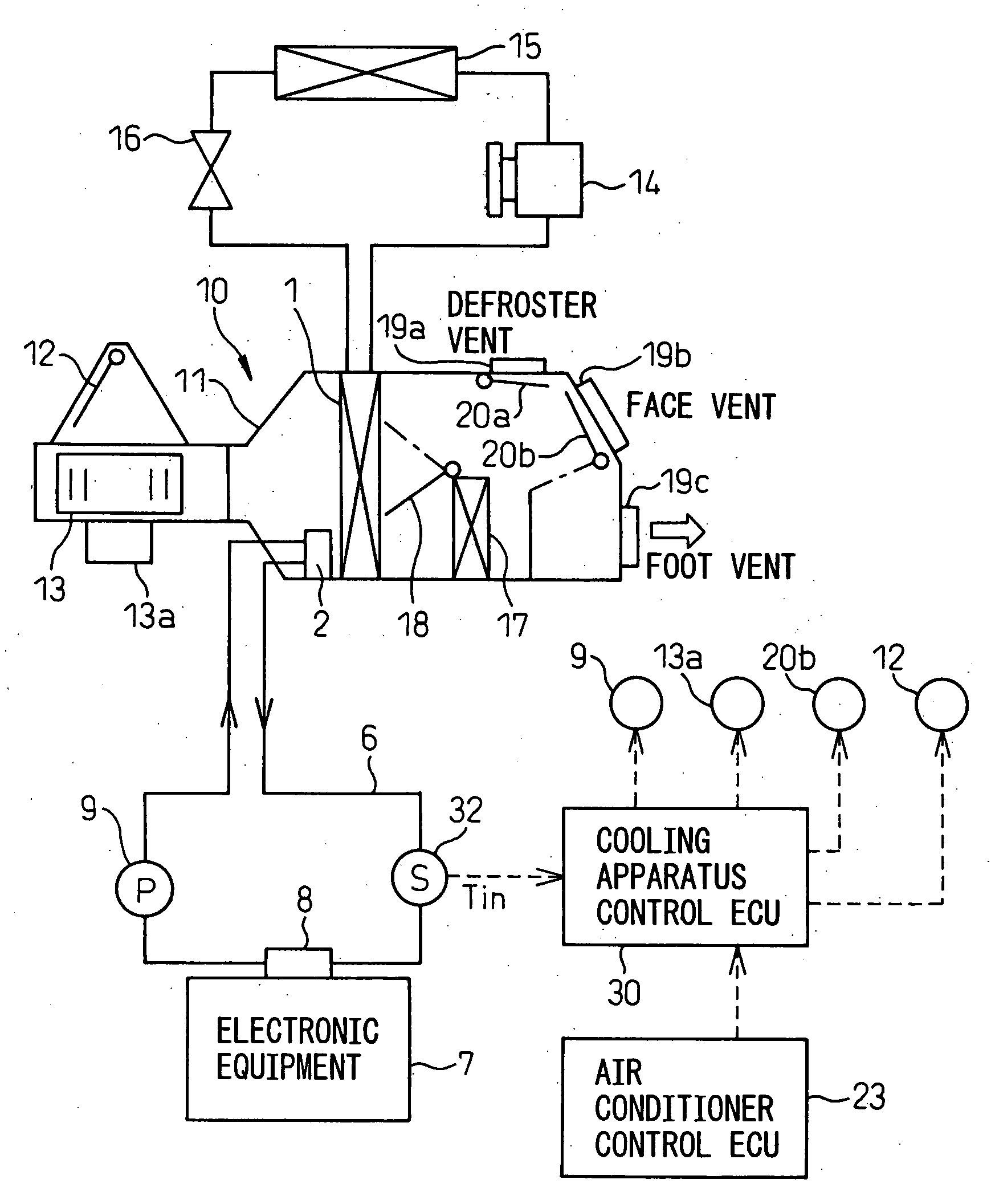
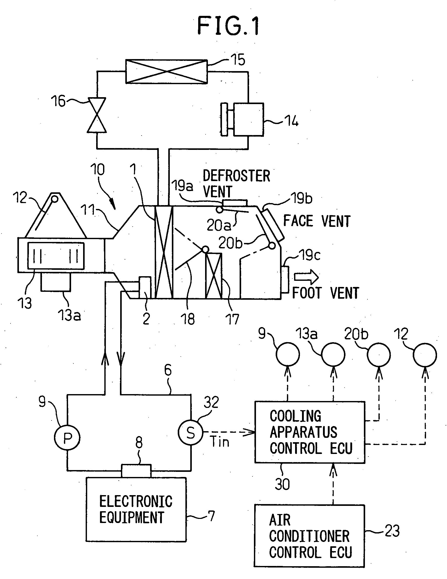
[0063]FIG. 1 is a schematic view showing the construction of a brine type cooling apparatus according to the first embodiment of the invention.

[0064]A brine type cooling apparatus according to this embodiment is to be mounted to a vehicle that is equipped with a vehicle air conditioner, and comprises a heat absorbing member 8 for absorbing heat from an electronic equipment 7 to be cooled, a heat radiating member 2 for discharging the heat absorbed by the heat absorbing member 8, a brine pipeline 6 and a circulation pump 9 for circulating the brine between the heat absorbing member 8 and the heat radiating member 2, an inlet water temperature sensor 32 for detecting brine temperature Tin on the inlet side of the electronic equipment 7, and a cooling apparatus control ECU 30 as means for controlling the cooling apparatus. The brine 60 is a heat exchanging medium, for example a liquid, mainly consisting of fluoride.

[0065]On the other hand, as the vehicle air conditioner, an air conditi...

second embodiment

[0091]FIG. 5 is a schematic view showing a brine type cooling apparatus according to a second embodiment of the invention. In FIG. 5, like constituents as in FIG. 1 are denoted by same reference numerals.

[0092]Although, in the first embodiment, the heat radiating member 2 is disposed in the air conditioning case 11, the heat radiating member 2 is disposed outside the air conditioning case 11 in this second embodiment.

[0093]This heat radiating member 2 is in contact with the evaporator 1 so as to permit heat conduction to the evaporator 1.

[0094]Specifically, for example, as shown in FIG. 6, in the case of tube fin structure in which the evaporator 1 has a tank section in communication with a tube, the heat radiating member 2 is disposed in contact with the tank section located on the lower side of the evaporator 1 in the Figure.

[0095]The heat radiating member 2 has a passage for brine 60 formed therein, and is connected to the inlet brine pipeline 4 and the outlet side brine pipeline...

third embodiment

[0100]FIG. 9 is a schematic view showing a brine type cooling apparatus according to the third embodiment, and in FIG. 9, like constituents as in FIG. 1 are denoted by the same reference numerals.

[0101]In this third embodiment, besides the defroster vent 19a, the face vent 19b, and the foot vent 19c, there is provided a waste heat vent 19d together with a waste heat door 20c for opening / closing the waste heat vent 19d.

[0102]The waste heat vent 19d is disposed at a position where the occupant is not directly exposed to the wind, so that the occupant is not aware of the wind from the vent. The position where the occupant is not directly exposed to the wind is, for example, a position where the wind is blown out of the room, or a position in the room where the wind is directed to the windshield or to the feet of the occupant. The waste heat door 20c is connected to the output side of the cooling apparatus control ECU 30, so that opening / closing of the waste heat vent 19d by means of t...


PUM


Abstract

A brine-type cooling apparatus applied to a vehicle equipped with a vehicle air conditioning case 11, a blower 13, and an air conditioner control ECU 23 as air conditioner controlling means, said brine type cooling apparatus comprising a heat absorbing member 8 for absorbing heat from an electronic equipment 7, a heat radiating member 2 for discharging the absorbed heat, a brine pipeline 6 and a circulation pump 9, and a cooling apparatus control ECU 30 as cooling apparatus controlling means. Even when the air conditioner control ECU 23 stops the blower 13 as air conditioner control, an air flow rate is controlled to set an airflow rate of the blower 13 to a predetermined flow rate based on the brine temperature detected by an inlet water temperature sensor 32.

Description

BACKGROUND OF THE INVENTION[0001]1. Technical Field of the Invention[0002]The present invention relates to a brine-type cooling apparatus, used in vehicle, for cooling an object to be cooled such as vehicle-mounted electronic equipment.[0003]2. Description of the Related Art[0004]In recent years, the amount of electronic equipment mounted on a vehicle, such as audio equipment, various ECUs (electronic control units), a thin film transistor liquid crystal display (TFT), and a head-up display, etc., has increased such that, due to increase of overall heat generation of this electronic equipment as well as increase of heat density resulting from size reduction of various equipment, an adequate cooling capability has become more and more necessary.[0005]At present, efficient natural heat radiation or forced air cooling using a fan is employed for cooling these electronic equipments. In addition, it is also envisaged to utilize a water cooling apparatus as shown in Japanese Patent Public...

Claims


Application Information

Patent Timeline
IPC IPC(8): F25D17/02B60H1/32F25D23/12
CPCB60H1/00021B60H1/00271B60H1/143B60H2001/00099H05K7/20881B60H2001/00614B60H2001/00928F28D1/0408B60H2001/00307B60H1/32281
Inventor FUJII, TAKAHISAITO, YUJINIIMI, YASUHIKOYAMAMOTO, TAKASHIKAMEI, EIICHIYOSHIDA, TAKAHIRO
Owner DENSO CORP
Why Eureka
Try Eureka