Reducing nitrogen concentration with in-situ steam generation

a technology of in-situ steam generation and nitrogen concentration, which is applied in the direction of basic electric elements, electrical apparatus, semiconductor devices, etc., can solve the problems of reducing the performance of transistors, reducing the nitrogen concentration, and slowing down the oxidation process, so as to achieve enhanced nitrogen removal

Inactive Publication Date: 2007-09-06
DONG ZHONG +2
View PDF9 Cites 4 Cited by
  • Summary
  • Abstract
  • Description
  • Claims
  • Application Information

AI Technical Summary

Benefits of technology

[0007] It is believed that the nitrogen removal can be enhanc

Problems solved by technology

The nitrogen presence is not always desirable, however, because nitrogen can cause degradation of the transistor's performance (due to an increased oxide charge for example).
When the peripheral areas are later oxidized to form the gate oxi

Method used


Image

  • Reducing nitrogen concentration with in-situ steam generation
  • Reducing nitrogen concentration with in-situ steam generation
  • Reducing nitrogen concentration with in-situ steam generation

Examples


Embodiment Construction

[0016] The embodiments described in this section illustrate but do not limit the invention. The invention is defined by the appended claims.

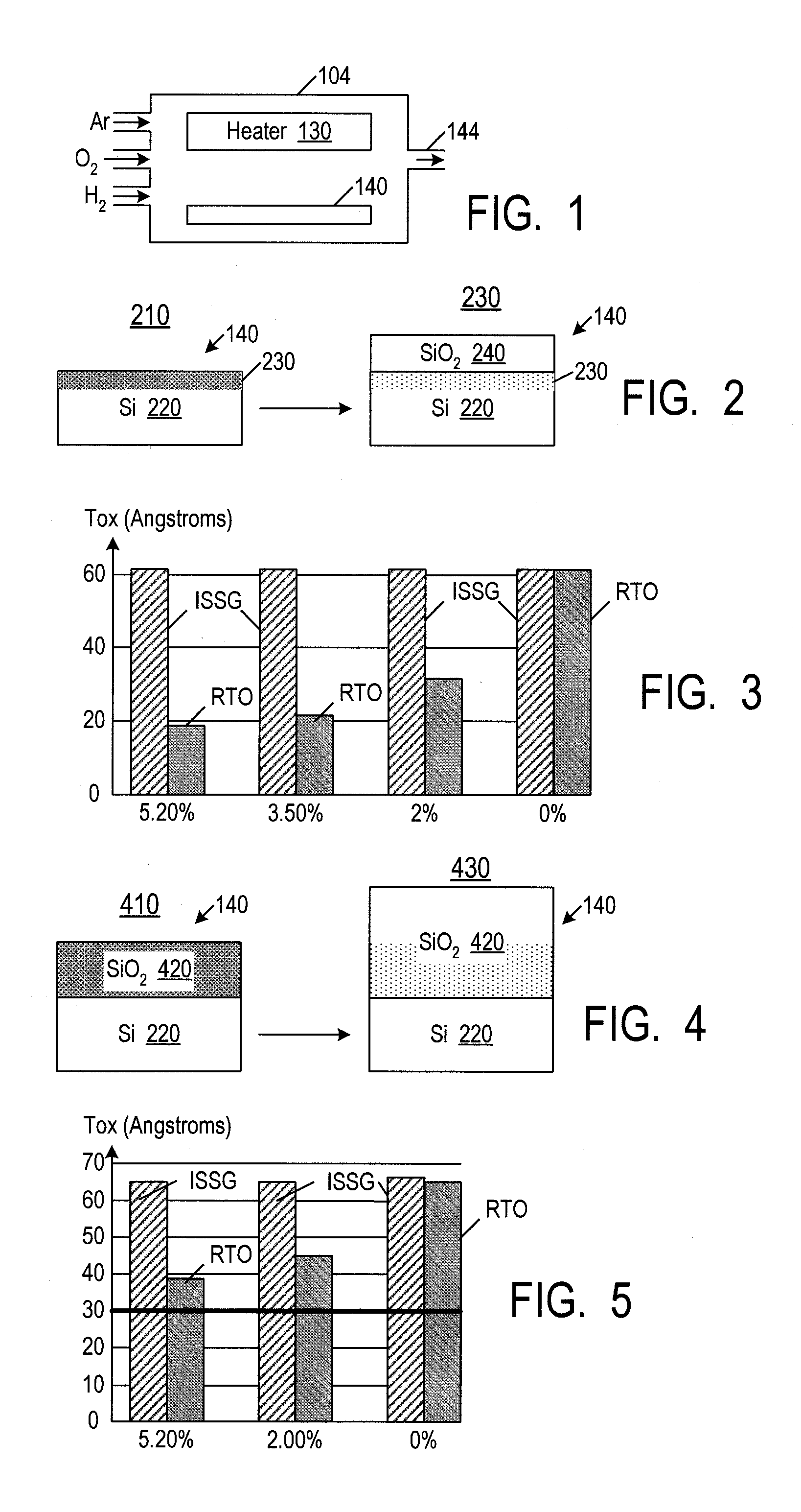
[0017]FIG. 1 illustrates a conventional ISSG chamber 104, such as described in U.S. patent application published as no. 2002 / 0146914 A1 on Oct. 10, 2002, filed by Huang et al., incorporated herein by reference. A silicon wafer 110 is placed in the chamber heated by a heater 130. Hydrogen, oxygen, and possibly other gases (e.g. argon or helium) are flown into the chamber. Hydrogen reacts with oxygen to form water vapor, i.e. H2O. The water vapor oxidizes silicon to form silicon dioxide (SiO2) and hydrogen. The gaseous by-products are pumped out via an exhaust path 144.

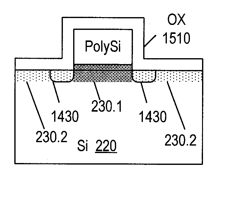
[0018] In FIG. 2, reference number 210 marks the silicon wafer 140 before the ISSG processing. The wafer contains a silicon substrate 220 (possibly, but not necessarily, monocrystalline silicon). The top region 230 of substrate 220 contains possibly unbound nitrogen atoms. Number ...


PUM


Abstract

In-situ steam generation (ISSG) is used to reduce the nitrogen concentration in silicon and silicon oxide areas.

Description

CROSS REFERENCE TO RELATED APPLICATIONS [0001] The present application is a division of U.S. patent application Ser. No. 11 / 365,013 filed on Mar. 1, 2006, incorporated herein by reference.BACKGROUND OF THE INVENTION [0002] The present invention relates to fabrication of integrated circuits, and more particularly to use of in-situ steam generation (ISSG) to form silicon oxide on regions containing silicon and / or silicon oxide and also containing nitrogen. [0003] Nitrogen has been introduced into MOS transistors' gate dielectrics formed of silicon dioxide because nitrogen impedes boron and phosphorus diffusing between the transistor's gate and the channel and source / drain regions. See e.g. U.S. patent application published as no. 2001 / 0003381 on Jun. 14, 2001, filed by Orlowski et al., incorporated herein by reference. The nitrogen presence is not always desirable, however, because nitrogen can cause degradation of the transistor's performance (due to an increased oxide charge for exa...

Claims


Application Information

Patent Timeline
IPC IPC(8): H01L29/76
CPCH01L21/28202H01L27/105H01L27/11526H01L29/7881H01L27/11546H01L29/0847H01L27/11536H10B41/40H10B41/44H10B41/49
Inventor DONG, ZHONGCHEN, CHILIANGCHEN, CHING-HWA
Owner DONG ZHONG
Why Eureka
Try Eureka