Cable reinforcement for flexible ducts

a flexible duct and reinforcement technology, applied in the direction of flexible pipes, mechanical equipment, pipes, etc., can solve the problems of reducing the efficiency of reinforcing chords, and reducing the resistance of reinforcing chords to high temperature and flame, so as to reduce the drag on fluids, improve efficiency, and minimize power and energy.

Inactive Publication Date: 2007-09-13
ARROWHEAD PROD
View PDF49 Cites 8 Cited by
  • Summary
  • Abstract
  • Description
  • Claims
  • Application Information

AI Technical Summary

Benefits of technology

[0009] To provide support and shape for the duct, the reinforcing cable may be attached to the either the exterior or interior of the wall in a helical fashion to provide the duct wall flexibility while tending to maintain the overall tubular form. In one preferred embodiment, the cable is helically wound about the exterior of the wall. Placing the cable on the exterior of the wall provides less drag on fluids traveling within the duct improving efficiency and minimizing the power and energy required to transfer the fluids. The cable is composed of a durable, flexible, heat resistant material. In one preferred embodiment, the cable is formed from stainless steel strands which contribute to increased flexibility and compressibility of the duct while simultaneously increasing flame resistance by reducing the amount of combustible materials. A coating of a polyimide varnish may be applied to the cable increasing both stiffness of the cable by virtue of the varnish and the flammability because of the polyimide properties.
[0010] To maximize safety and enhance durability, the duct may also encompass other embodiments that assist in providing flame resistance. In one preferred embodiment a thin rubber coating on a fiberglass fabric may be used to form the wall. Using fiberglass fabric that meets flammability standards serves to cut down on the amount of combustible material in the duct. In one embodiment, the fiberglass fabric side of the wall faces radially outwardly where it will be first to contact heated components of the carrier in the event of fire in nearby components. In the embodiments, the thin rubber coating may face the interior of the wall to decrease friction on fluid traveling within the duct.

Problems solved by technology

The ducts must then be sufficiently flexible to be threaded through circulation paths in an aerospace vehicle, often times bent and flattened during installation resulting in permanent deformation thus impinging on the efficiency of flow thereon.
It is known to those skilled in the art that in the event of combustion, the walls of any such ducts may well be exposed directly to flame and high temperature.
While less subject to permanent deformation upon bending, polymer reinforcing chords often do not exhibit resistance to high temperature and flame.
While serving to reduce twist in the duct under load, such resin spirals have limited resistance to combustion.
Such duct designs serve to resist compressibility but lack the ability to restore their profile adequately when deformed by external pressures.
While serving to prevent the formation of shrinkage cavities between layers, these layers add to the combustibility content of the duct and pose a risk for flammability.
Additionally, the single wire reinforcement used contributes to resiliency problems and subjects the ducts to collapse without restoration after exposure to the environmental stresses within for example, an airframe.
However, these hoses also include a higher amount of combustible materials and suffer from heavy weight that is not conducive to the economics of load management in airplane construction.

Method used


Image

  • Cable reinforcement for flexible ducts
  • Cable reinforcement for flexible ducts
  • Cable reinforcement for flexible ducts

Examples


Embodiment Construction

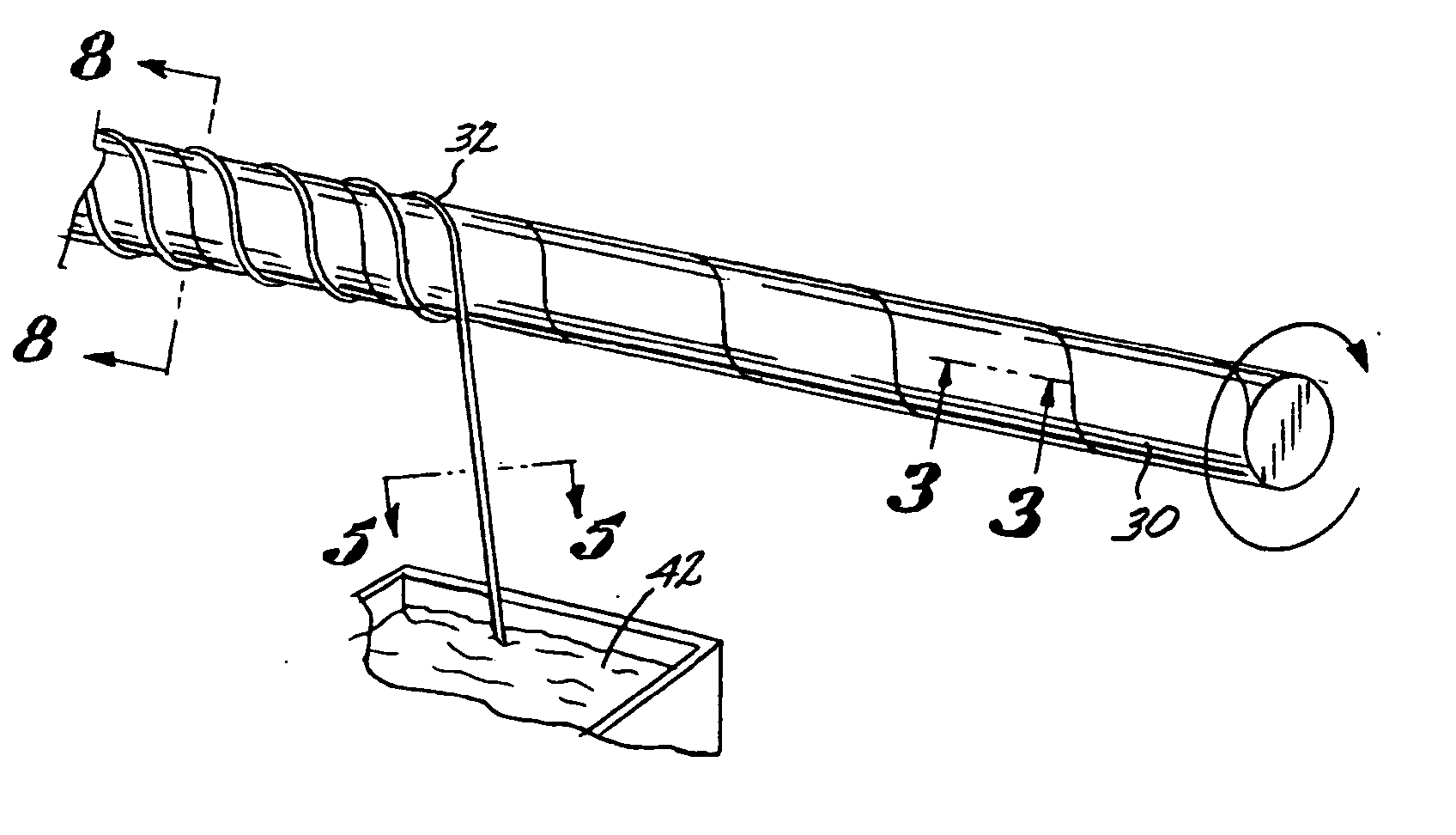
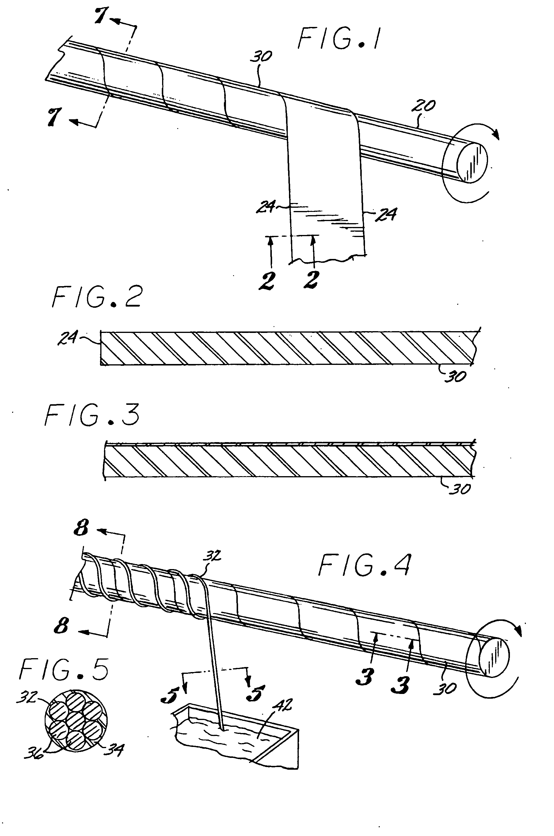
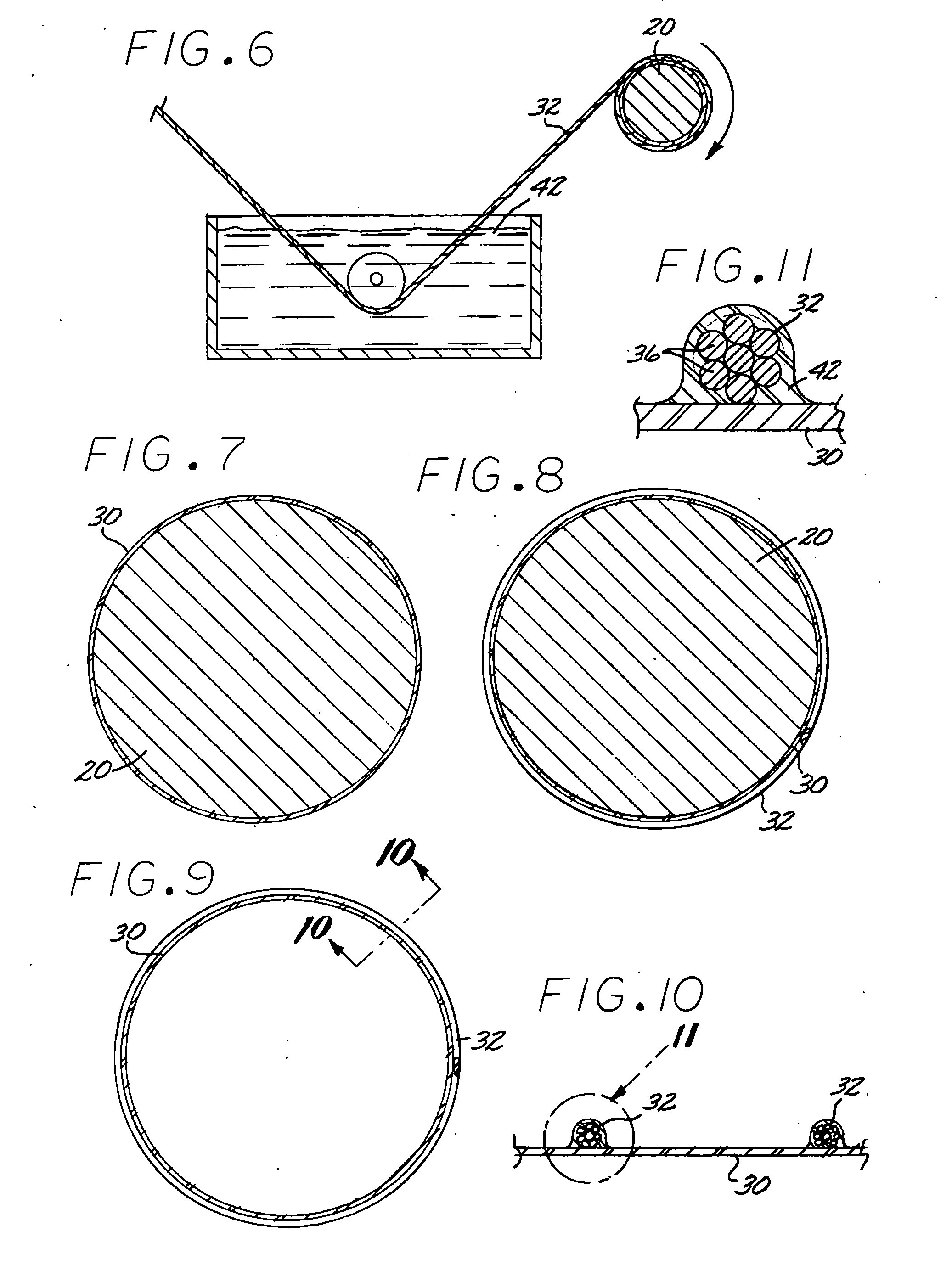
[0029] The lightweight flexible flame resistant reinforced duct 22 of the present invention includes, a flexible membrane tube wall 30 constructed of a polymer film which may be on fiberglass fabric and encased in a multi-strand spiral cable 32 attached along the wall to provide distension and reinforcement. Referring to FIG. 5, the cable 32 is formed by grouping multiple strands together and may be coated in a polyimide varnish 34 before it is attached to the to the wall 30 by means of an adhesive 42, (FIGS. 10-11).

[0030] In one preferred embodiment, referring to FIGS. 1 and 15, the duct is formed by wrapping the edges of the membrane 30 over a mandrel 20 and sealing any seams with an adhesive. Once the tube wall is formed, the metallic cable 32 is wrapped about the membrane and mandrel and attached to the membrane by an adhesive 42.

[0031] Commercial transport aircraft typically make use of flexible ducting for transport of various fluids within the aircraft frame for controlling...


PUM


Abstract

A flexible fire resistant duct constructed of a flexible fire resistant membrane forming a tube and reinforced with a metallic multi-strand cable.

Description

FIELD OF THE INVENTION [0001] The present invention relates to a flexible fire resistant duct for circulating fluid to or from various locations within a common carrier. BACKGROUND OF THE INVENTION [0002] Common carriers such as aircraft, automobiles, naval vessels and trains require the circulation of air and gases within specific areas for controlling the environment and to vent certain areas. To accomplish such circulation, many vehicles employ ducts to carry and circulate the gas from one area to another. The use of ducts to circulate gas is commonly known as an environmental control system (“ECS”). The ducts carry positive and sometimes negative fluid pressure. In practice, these ducts are installed as the airplane or air ship reaches the final stages of assembly and most components have already been installed thereby leaving little space for installation and manipulation of the duct. The ducts must then be sufficiently flexible to be threaded through circulation paths in an ae...

Claims


Application Information

Patent Timeline
Patent Type & Authority Applications(United States)
IPC IPC(8): F16L11/00
CPCF16L11/125F16L11/10
Inventor TOMERLIN, REGLARNER, DAVID S.SONJU, THEODORE R.
Owner ARROWHEAD PROD
Why Eureka
Try Eureka