Trench type schottky rectifier with oxide mass in trench bottom

Active Publication Date: 2007-09-13
INFINEON TECH AMERICAS
View PDF1 Cites 13 Cited by
  • Summary
  • Abstract
  • Description
  • Claims
  • Application Information

AI Technical Summary

Benefits of technology

[0011]The introduction of the insulation spacer(s), which are preferably silicon dioxide, will alter the electric field distribution in the trench regions as well as in the Mesa regions, to improve the blocking capability of the unit cell.
[0012]Thus, the presence of the oxide spacer at the bottom of the trench region, which is then filled with a semiconductor material (

Problems solved by technology

However, the blocking capability of the trench barrier Schottky is limited by punch-trough phenomena in the depletion layer at the transition zone

Method used


Image

  • Trench type schottky rectifier with oxide mass in trench bottom
  • Trench type schottky rectifier with oxide mass in trench bottom
  • Trench type schottky rectifier with oxide mass in trench bottom

Examples


Embodiment Construction

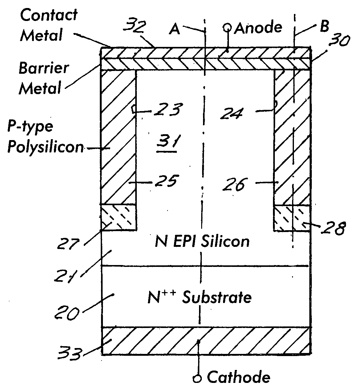
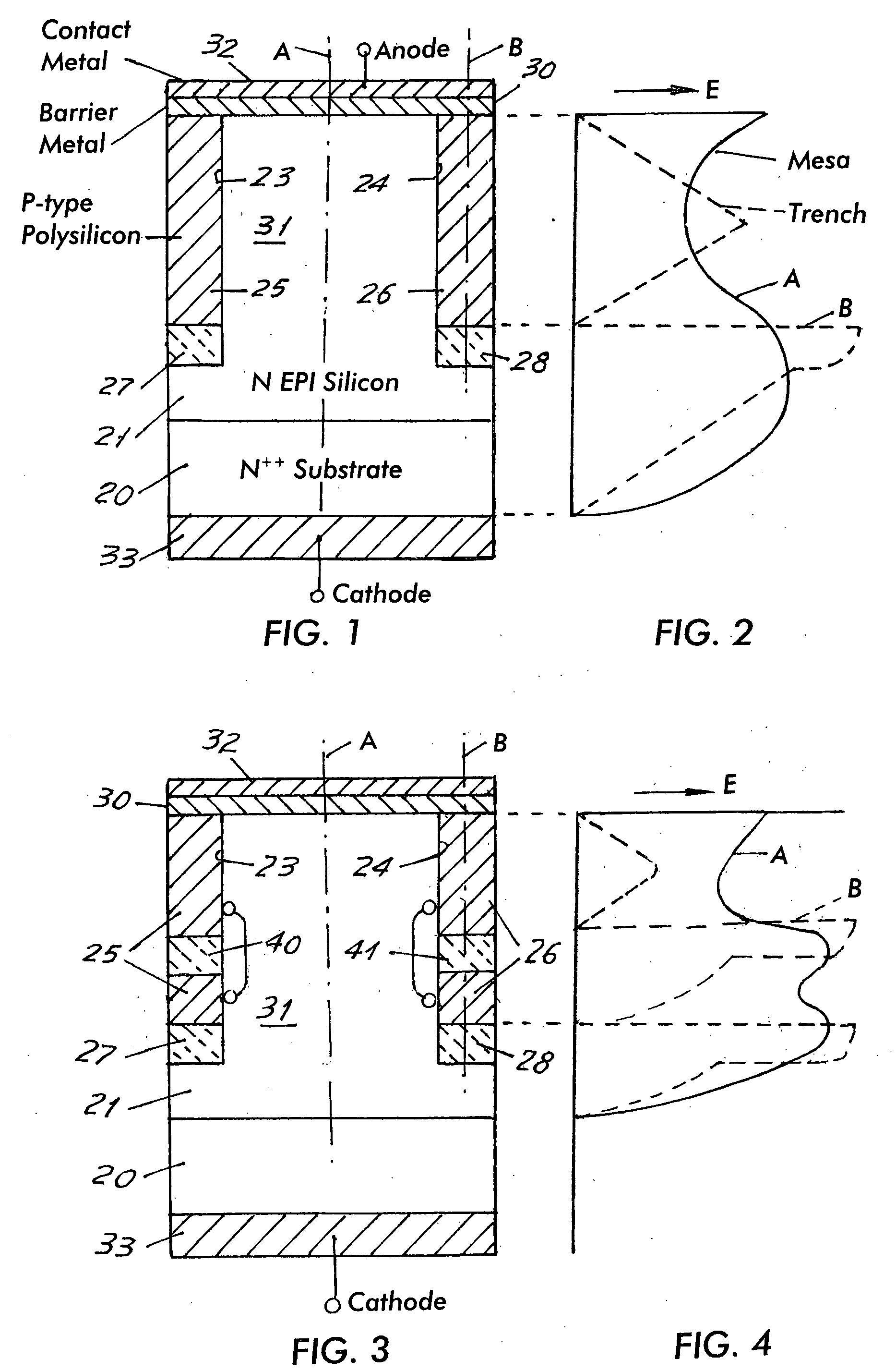
[0020]Referring first to FIG. 1, there is shown an elemental cell of a device made in accordance with the invention. It will be understood that a wafer will contain a large number of identical cells over its area. The cells may be in parallel spaced trenches or in trenches of other cross-sections such as circular, rectangular, or the like.

[0021]The cell of FIG. 1 has a high concentration (N++) silicon substrate 20 which has a lower concentration N type epitaxial layer 21 grown on its upper surface.

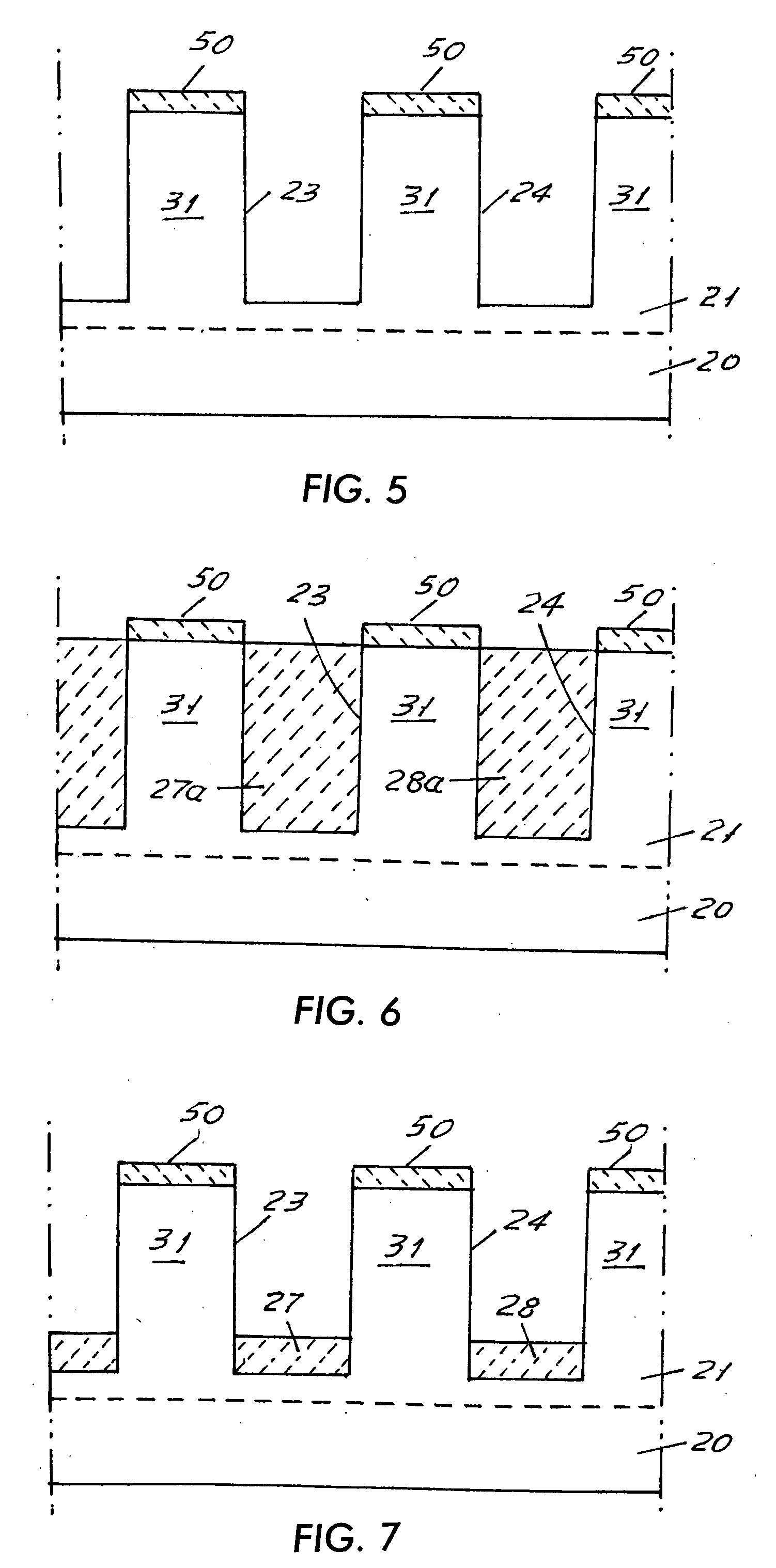
[0022]A plurality of parallel grooves or trenches (shown as half grooves 23 and 24 in FIG. 1) are etched into layer 21 and are filled with doped semiconductor (for example P type polysilicon) masses 25 and 26 respectively.

[0023]In accordance with the invention, as will be later discussed, grooves 23, 24 have their bottoms filled with oxide masses 27 and 28, (or bubbles) which are below polysilicon masses 25 and 26 respectively.

[0024]A suitable Schottky barrier metal 30, which may be a meta...


PUM


Abstract

A trench type junction barrier rectifier has silicon dioxide spacers at the bottom of trenches in a silicon surface and beneath the bottom of a conductive polysilicon filler in the trench. A Schottky barrier electrode is connected to the tops of the mesas and the tops of the polysilicon fillers. Further oxide spacers may be formed in the length of the polysilicon fillers.

Description

RELATED APPLICATION[0001]This application claims the benefit of U.S. Provisional Application No. 60 / 779,835, filed Mar. 7, 2006, the entire disclosure of which is incorporated by reference herein.FIELD OF THE INVENTION[0002]This invention relates to semiconductor devices and more specifically relates to a trench type Schottky rectifier with increased blocking voltage capability and a process for its manufacture.BACKGROUND OF THE INVENTION[0003]Trench Junction Barrier Schottky Rectifiers (TJBS Rectifiers) and Trench MOS Barrier Schottky (TMBS rectifiers) are well known structures capable of sustaining breakdown voltage higher than the theoretical Silicon limit in a planar structure. As will be later seen in the novel structure of the invention, the trenches are filled with doped polysilicon or other semiconductor material with an n or p doping concentration. The proposed structure also incorporates buried oxide regions into the trenches and the Schottky interface is formed at the top...

Claims


Application Information

Patent Timeline
IPC IPC(8): H01L31/07H01L27/095
CPCH01L29/872H01L27/0817
Inventor SANFILIPPO, CARMELOCARTA, ROSSANO
Owner INFINEON TECH AMERICAS
Why Eureka
Try Eureka