
Electrically programmable fuse structures with narrowed width regions configured to enhance current crowding and methods of fabrication thereof

a technology of fuses and narrow widths, applied in the field of fuses, can solve the problems of inability to shrunk the laser fuse size indefinitely, the difficulty of ablative laser-blown fuse implementation, and the limited relative size of laser fuses, etc., to achieve the effect of enhancing current crowding

Inactive Publication Date: 2007-09-13
IBM CORP
View PDF20 Cites 24 Cited by
  • Summary
  • Abstract
  • Description
  • Claims
  • Application Information

AI Technical Summary

Benefits of technology

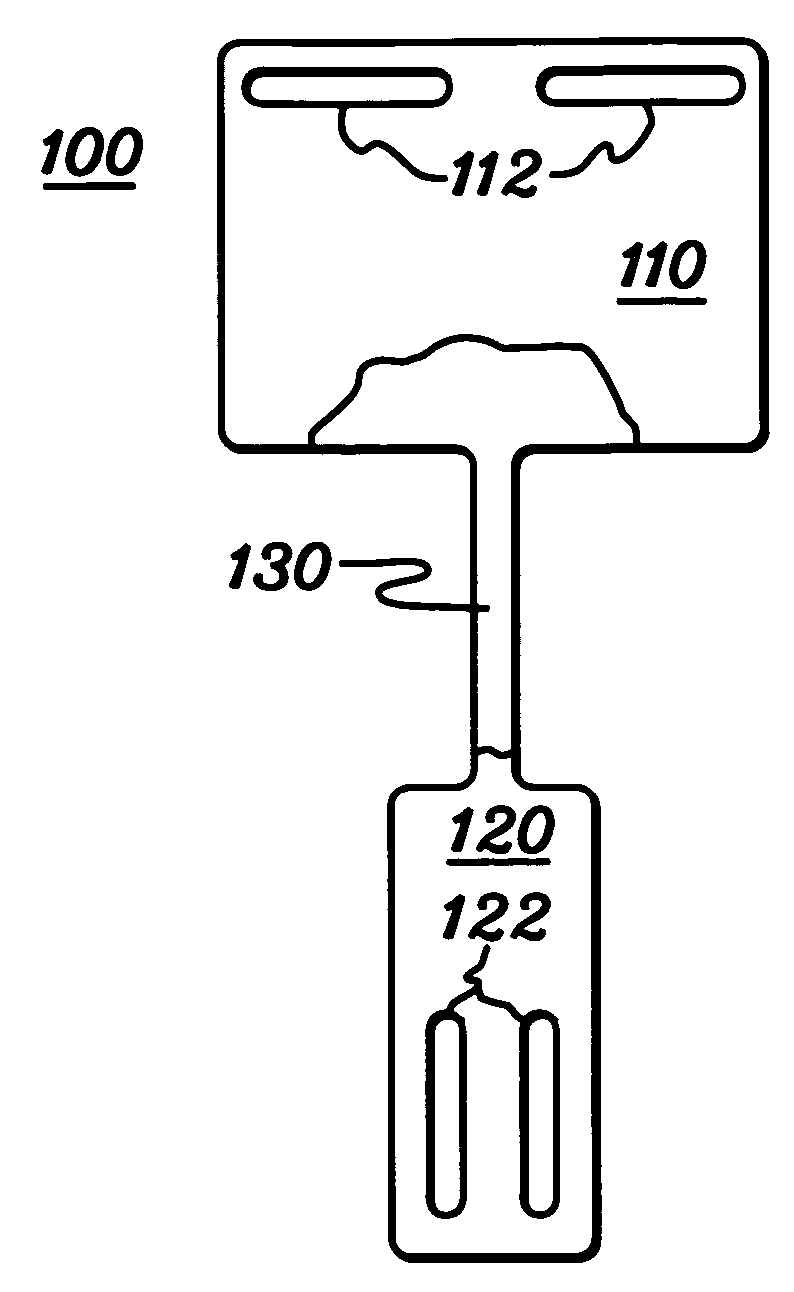
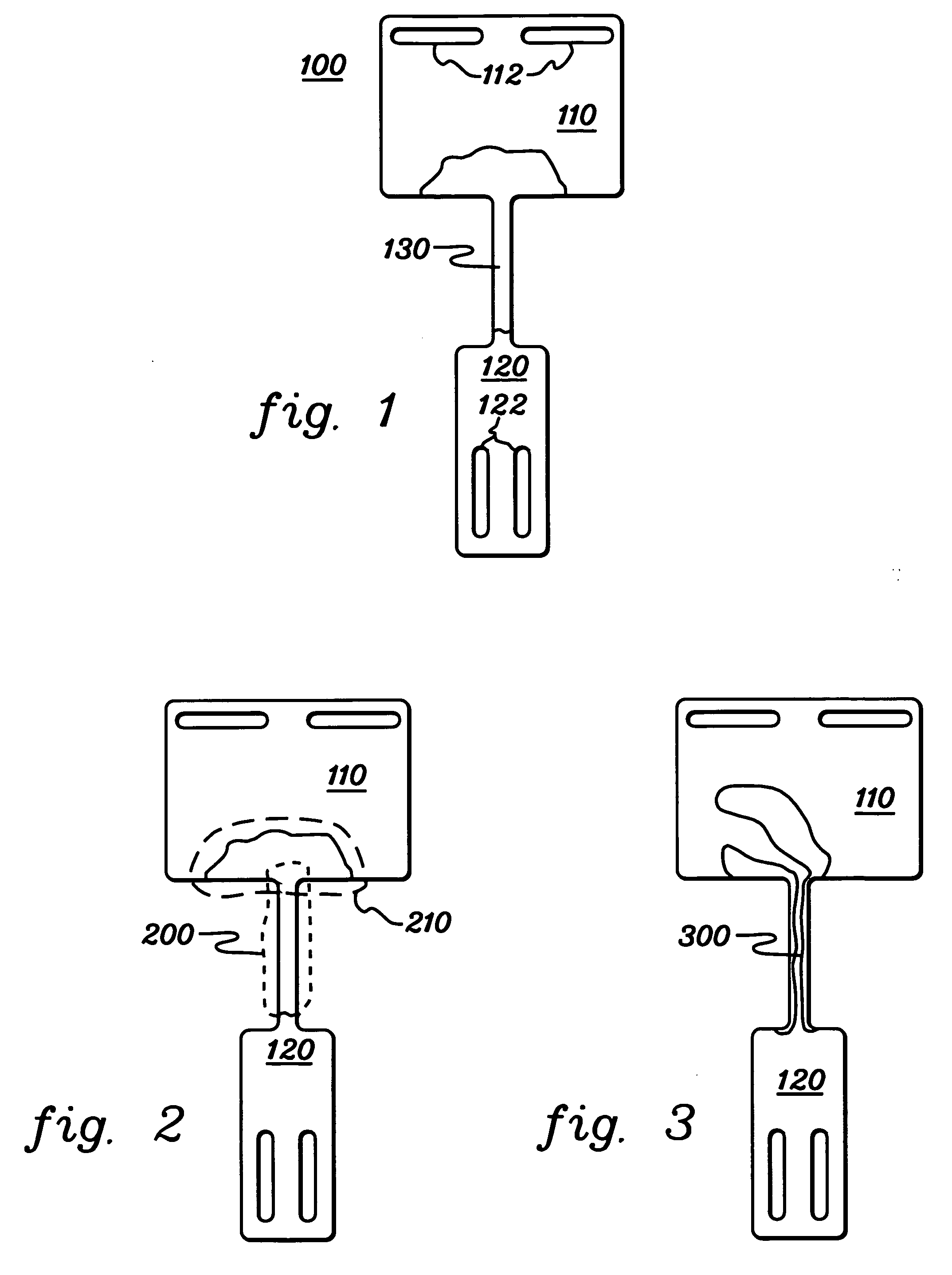
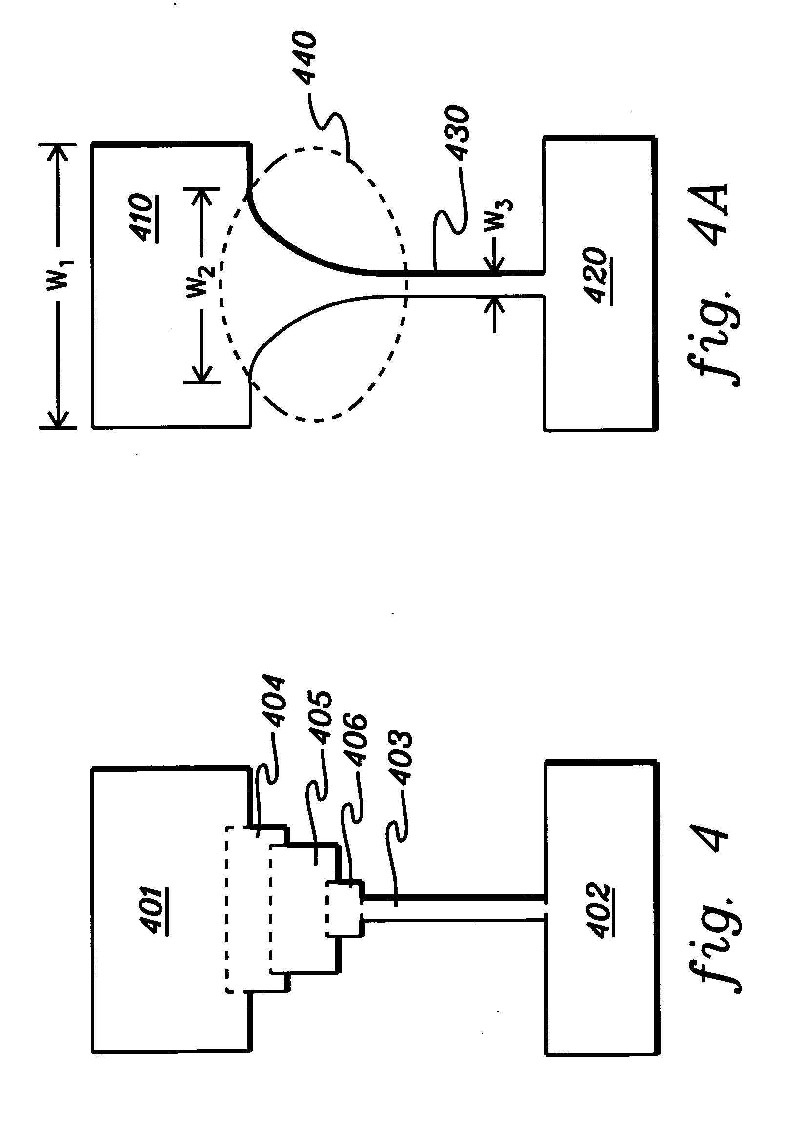
[0009] Briefly summarized, the present invention comprises in one aspect an electrically programmable fuse for an integrated circuit. The fuse includes a first terminal portion and a second terminal portion interconnected by an elongate fuse element. The first terminal portion has a maximum width greater than the maximum width of the elongate fuse element, and the fuse includes a narrowed width region where the first terminal portion and the elongate fuse element interface. The narrowed width region extends at least partially into and comprises part of the first terminal portion, and a width of the first terminal portion in the narrowed width region is less than the maximum width of the first terminal portion to enhance current crowding therein.
[0011] In a further aspect, a method of fabricating an electrically programmable fuse for an integrated circuit is provided. The method includes: forming a fuse on a support structure, the fuse comprising a first terminal portion and a second terminal portion interconnected by an elongate fuse element; and wherein the first terminal portion has a maximum width greater than a maximum width of the elongate fuse element, and the fuse includes a narrowed width region where the first terminal portion and elongate fuse element interface, the narrowed width region extending at least partially into and comprising part of the first terminal portion, and wherein a width of the first terminal portion in the narrowed width region is less than the maximum width of the first terminal portion to enhance current crowding therein.
[0012] In a yet further aspect, a method of fabricating an electrically programmable fuse for an integrated circuit is provided. This method includes: forming a fuse on a support structure, the fuse comprising a first terminal portion and a second terminal portion interconnected by an elongate fuse element; and wherein the elongate fuse element has a maximum width and includes a restricted width region wherein width of the elongate fuse element within the restricted width region is less than the maximum width of the elongate fuse element to enhance current crowding therein, and a length of the restricted width region is less than a total length of the elongate fuse element.

Problems solved by technology

As devices continue to shrink, the relative size of these laser fuses is limited by the wavelength of the laser employed.
Therefore, the size of the laser fuse cannot be shrunk indefinitely.
Thus, ablative laser-blown fuses become more difficult to implement due to the silicon space required to implement the fuses and avoid damage to neighboring circuits.
Further, repairing an integrated circuit chip by open circuiting thousands of laser programmable fuses is a time consuming process.
Although electrically programmable e-fuses provide these noted benefits, integration with standard CMOS processing has been problematic.
Furthermore, obtaining a tight distribution of open circuiting voltages derived using today's normal operating voltages continues to be challenging.
As operating voltages continue to be aggressively scaled down with each succeeding generation of integrated circuit technology, obtaining sufficiently high voltages for programming an e-fuse can tax the electrical operating limits of the technology, and increase circuit complexity, for example, due to the need for charge pumps.

Method used


Image

  • Electrically programmable fuse structures with narrowed width regions configured to enhance current crowding and methods of fabrication thereof
  • Electrically programmable fuse structures with narrowed width regions configured to enhance current crowding and methods of fabrication thereof
  • Electrically programmable fuse structures with narrowed width regions configured to enhance current crowding and methods of fabrication thereof

Examples


Embodiment Construction

[0028] Typically, the resistance of programmed prior art polycide e-fuses is highly variable. Large variations in the electrical characteristics of the driver transistors due to threshold voltage (Vt) variations are commonly encountered. This results in variations in programming current, which in turn causes the length of the opened gap (electromigration length of the silicide) in the fuse element to vary. Since read current is traditionally forced through the silicon underlying the blown fuse element, the overall resistance of the programmed fuse will also vary. This dependence of the programmed resistance on the electromigration length of the silicide can lead to difficulties in correctly sensing the state of a programmed e-fuse.

[0029] In addition, recently developed e-fuse structures take advantage of electromigration (EM) effects to address certain of the above-noted problems of achieving scaling of programming voltage. Briefly, the EM effect, caused by a positive divergence of...


PUM


Abstract

Electrically programmable fuse structures and methods of fabrication thereof are presented, wherein a fuse includes first and second terminal portions interconnected by an elongate fuse element. The first terminal portion has a maximum width greater than a maximum width of the fuse element, and the fuse includes a narrowed width region where the first terminal portion and fuse element interface. The narrowed width region extends at least partially into and includes part of the first terminal portion. The width of the first terminal portion in the narrowed region is less than the maximum width of the first terminal portion to enhance current crowding therein. In another implementation, the fuse element includes a restricted width region wherein width of the fuse element is less than the maximum width thereof to enhance current crowding therein, and length of the restricted width region is less than a total length of the fuse element.

Description

CROSS-REFERENCE TO RELATED APPLICATIONS [0001] This application contains subject matter which is related to the subject matter of the following co-filed, commonly assigned applications, each of which is hereby incorporated herein by reference in its entirety: [0002]“Electrically Programmable Fuse Structures with Terminal Portions Residing at Different Heights, and Methods of Fabrication Thereof”, by Booth et al., U.S. Ser. No. ______, co-filed herewith (Attorney Docket No.: ROC920050384US1); [0003]“Electronic Fuse with Conformal Fuse Element Formed Over a Freestanding Dielectric Spacer”, by Hsu et al., U.S. Ser. No. ______, co-filed herewith (Attorney Docket No.: ROC920050385US1); and [0004]“Electrically Programmable π-Shaped Fuse Structures and Methods of Fabrication Thereof”, by Booth et al., U.S. Ser. No. ______, co-filed herewith (Attorney Docket No. ROC920050386US1).TECHNICAL FIELD [0005] The present invention relates in general to semiconductor structures and methods of fabric...

Claims


Application Information

Patent Timeline
Patent Type & Authority Applications(United States)
IPC IPC(8): H01L29/00
CPCH01L23/5256H01L2924/0002H01L2924/00
Inventor BOOTH, ROGER A. JR.MANDELMAN, JACK A.TONTI, WILLIAM R.
Owner IBM CORP
Learn More