Method and apparatus for slew rate control

a technology of slew rate and control method, applied in the direction of pulse technique, amplitude demodulation, generating/distributing signals, etc., can solve the problem of inability to adjust very precisely, the maximum output rate of the buffer is limited, and the conventional rise and fall time control technique is sensitive to process changes,

Inactive Publication Date: 2007-09-13
AVAGO TECH WIRELESS IP SINGAPORE PTE
View PDF7 Cites 19 Cited by
  • Summary
  • Abstract
  • Description
  • Claims
  • Application Information

AI Technical Summary

Benefits of technology

[0008] According to another aspect of the invention, compensation is optionally provided for variations in, for example, process corner, supply voltage, aging and operating temperature. The compensation can be performed by generating an analog control voltage,

Problems solved by technology

If the slew rate of a high speed serial output buffer is too low, then the maximum output rate of the buffer will be limited.
However, if the slew rate is too high, then the frequency spectrum of the output waveform will have significant high frequency components, causing the buffer to act as a source o

Method used


Image

  • Method and apparatus for slew rate control
  • Method and apparatus for slew rate control
  • Method and apparatus for slew rate control

Examples


second embodiment

[0026]FIG. 5 illustrates an output buffer 500 in accordance with the present invention. The output buffer 500 of FIG. 5 includes the output buffer 300 of FIG. 3, as well as a PVT compensation circuit 510. In one exemplary embodiment, the PVT compensation circuit 510 comprises a delay-locked loop (DLL) that generates an analog control voltage, VSRCT. The control voltage, VSRCT, compensates for PVT variations by adjusting the delay, TD, of each of M delay elements 520, such that the total delay, M×TD, is approximately equal to the period of the main clock, TCLK. The DLL 510 also comprises a phase detector 530 and an integrator 540 in a known manner. Generally, each individual delay element in the DLL 510 is substantially matched to the delay elements 320 from the rise and fall time control circuit 300. Thus, TD=TCLKM.

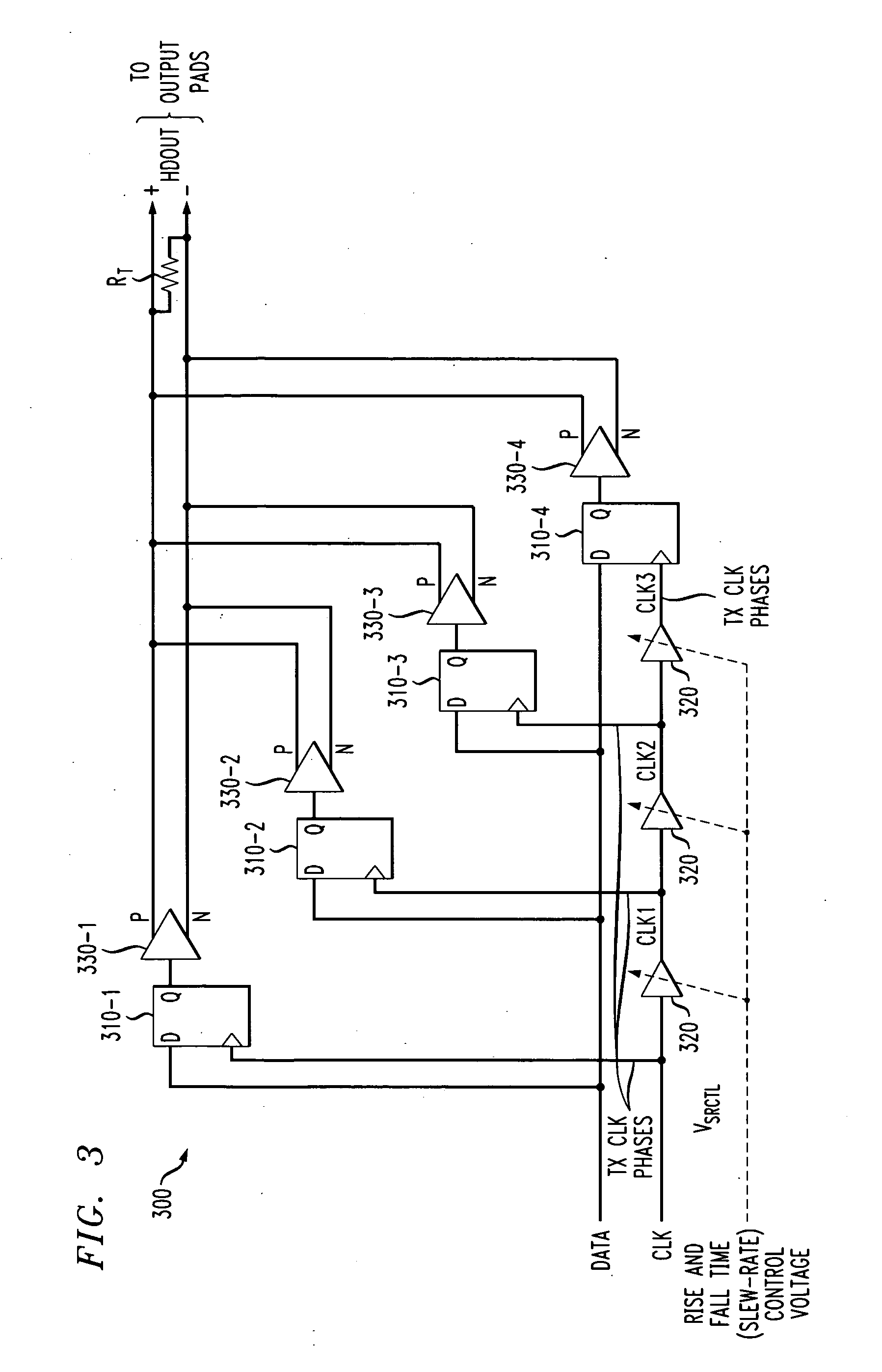
[0027] Since the rise time of the HDOUT waveform (see FIG. 3) is approximately equal to the delay through the three delay cells 320, then the total rise (and fall time),...

third embodiment

[0032]FIG. 6 illustrates an output buffer 600 in accordance with the present invention, that provides finer control of the rise time, TR, than the embodiment of FIG. 5. In the embodiment of FIG. 6, a gain stage 610, having a gain, G, where the G is much less than 1 but may be positive or negative, is employed to allow small adjustments to the rise and fall times. Thus, the control voltage, VSRCT, may be expressed as follows:

VSRCT=(1+G)VCTRL

where G is a small number (positive or negative).

[0033] If the delay of each of the delay cells in the DLL is equal to

TD=AVCTRLα

(where a typical value for a would be −½), then, the derivative of TD with respect to the DLL control voltage, VCTRL, is ⅆTDⅆVCTRL=α⁢ ⁢AVCTRLα-1=α⁢TDVCTRL.

Intuitively, this expression suggests that a small change to VCTRL results in a corresponding small change in TD.

[0034] For example, if α equals −½ and δVCTRL is a 1% change in VCTRL, then TD would change by approximately: δ⁢ ⁢TD=(ⅆTDⅆVCTRL)⁢δ⁢ ⁢VCTRL=α⁢ ⁢TD⁢δ⁢...


PUM


Abstract

Methods and apparatus are provided for controlling at least one of a rise time and a fall time of a signal. A plurality of time shifted clock signals are generated; and a received data signal is sampled using a plurality of parallel data paths, where each of the data paths are controlled by a corresponding one of the plurality of time shifted clock signals. The plurality of time shifted clock signals can be generated, for example, by at least one delay element. The plurality of parallel data paths can be substantially identical and comprise, for example, at least one latch or at least one flip flop. Compensation can optionally be provided for variations in, for example, process corner, supply voltage, aging and operating temperature.

Description

FIELD OF THE INVENTION [0001] The present invention is generally related to slew rate control techniques, and more particularly, to slew rate control techniques that do not exhibit data dependent jitter. BACKGROUND OF THE INVENTION [0002] Slew rate is an important characteristic of the design and operation of integrated circuit devices, especially output buffers in high speed serial transceivers. Generally, the slew rate is the rate at which the output from an electronic circuit or device can be driven from one limit to another limit over the dynamic range of the electronic circuit or device. For the output buffer of a serial transceiver, the slew rate is defined as (V1−V0) / TR for a rising output transition, and as (V1−V0) / TF for a falling output transition, where V0 and V1 are the output levels associated with a logic 0 and logic 1, respectively, and TR and TF are the output rise and fall times, respectively. If the slew rate of a high speed serial output buffer is too low, then th...

Claims


Application Information

Patent Timeline
IPC IPC(8): H03K19/00
CPCH03K5/01
Inventor ABEL, CHRISTOPHER J.MAO, WEIWEI
Owner AVAGO TECH WIRELESS IP SINGAPORE PTE
Why Eureka
Try Eureka