Error corrector for radar timing systems

a timing system and error correction technology, applied in the field of radar timing circuits, can solve problems such as introducing 1 cm range errors, and achieve the effect of reducing deviations

Inactive Publication Date: 2007-09-13
MCEWAN TECH
View PDF34 Cites 35 Cited by
  • Summary
  • Abstract
  • Description
  • Claims
  • Application Information

AI Technical Summary

Benefits of technology

[0012] The present invention overcomes the limitations of the various analog and digital timing techniques used to generate a swept phase clock by employing an error correction feedback loop that reduces deviations from a constant sweep rate. Errors, i.e., deviations are detected and fed back to a phase corrector in a high gain feedback system.

Problems solved by technology

A radar timing system having a constant sweep rate can be implemented with a direct digital synthesizer (DDS) that generates a receive clock that is offset from a transmit clock However, DDS timing errors can introduce 1 cm range error.

Method used


Image

  • Error corrector for radar timing systems
  • Error corrector for radar timing systems
  • Error corrector for radar timing systems

Examples


Embodiment Construction

[0036] A detailed description of the present invention is provided below with reference to the figures. While illustrative component values and circuit parameters are given, other embodiments can be constructed with other component values and circuit parameters. All U.S. patents and copending U.S. applications cited herein are herein incorporated by reference.

General Description

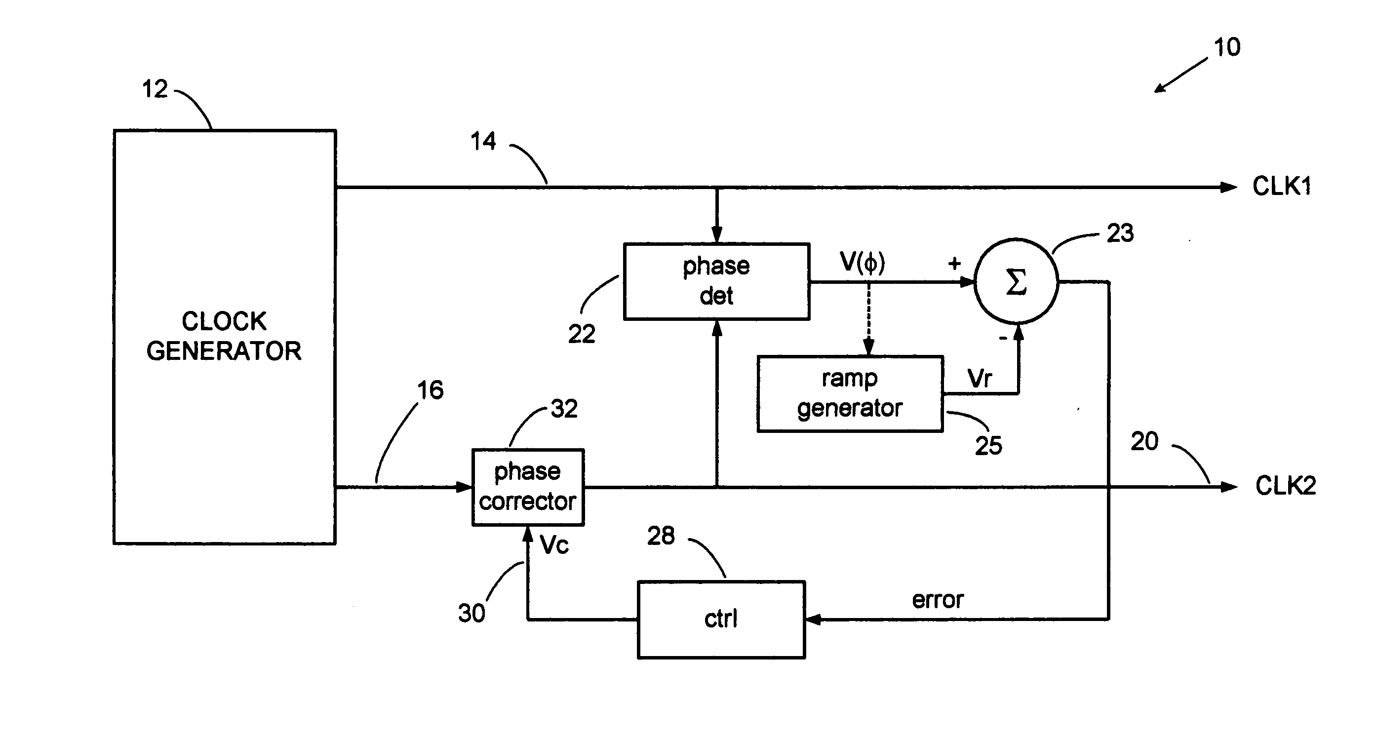
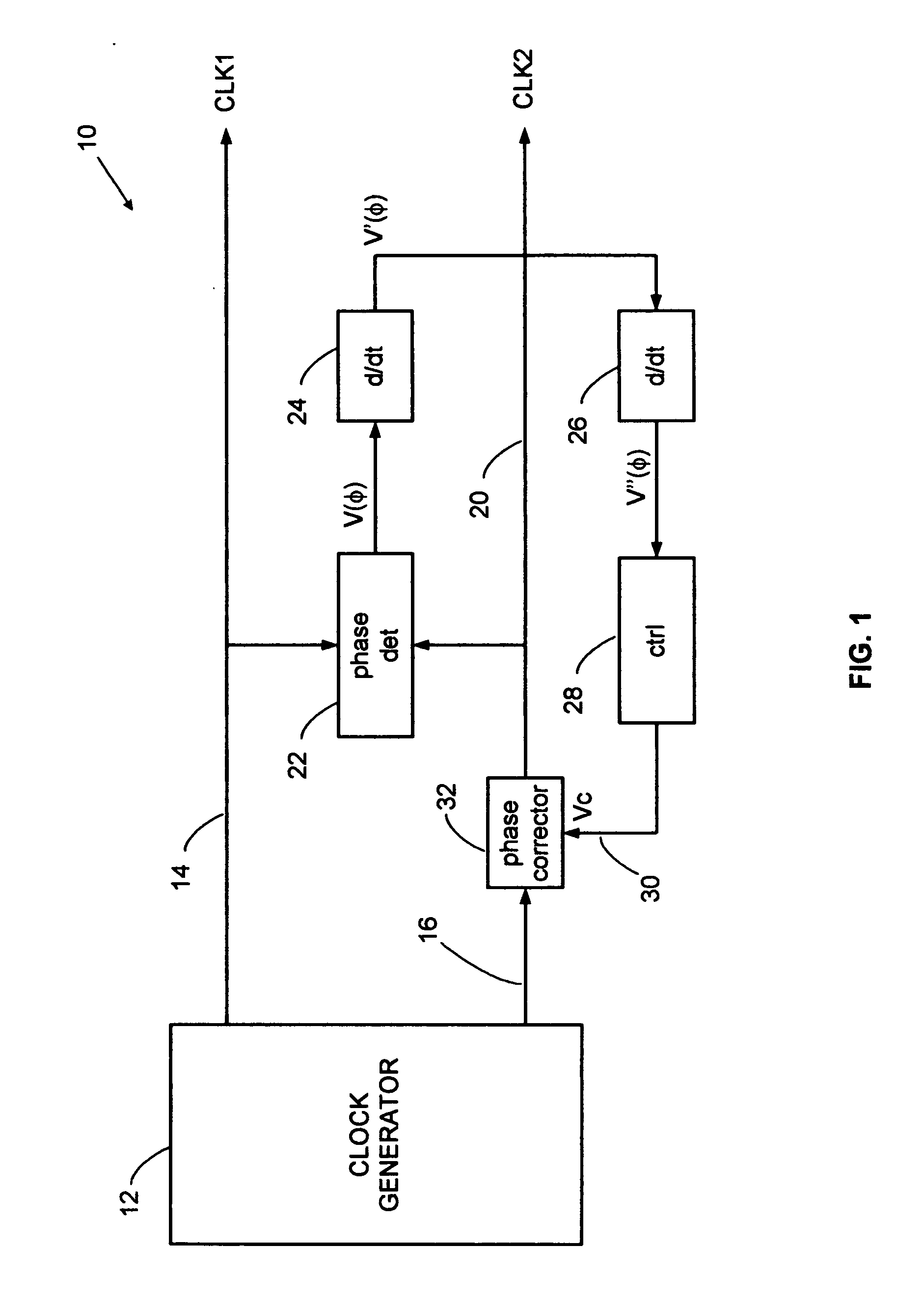
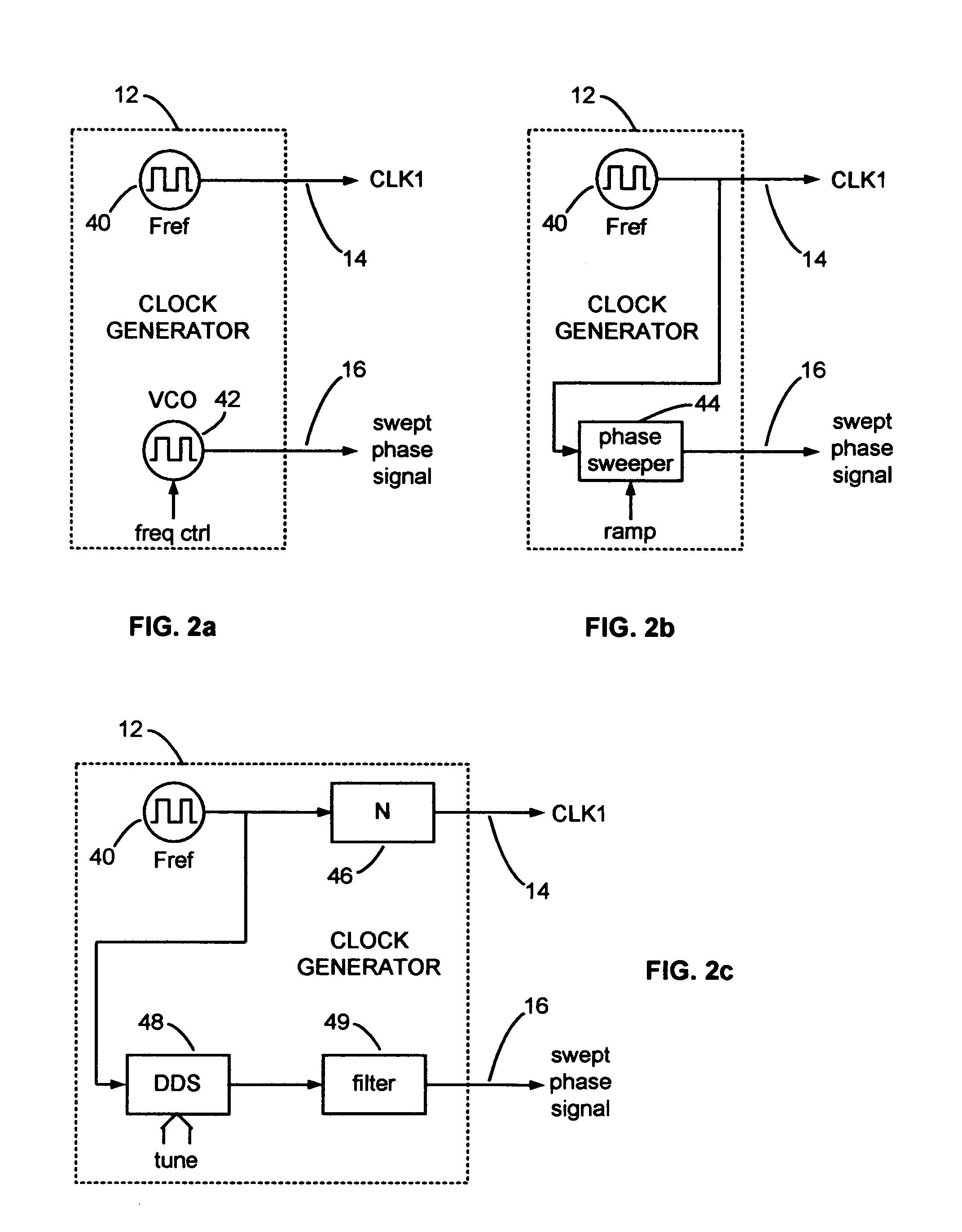
[0037] The present invention overcomes the accuracy limitations of a DDS based clock generator and other clock generators by correcting errors in phase slip on a continuous and instantaneous basis. A beneficial example embodiment, as disclosed herein, employs a phase detector coupled directly between radar transmit and receive clocks, rather than through counter chains that are customary in PLL circuits, to produce a voltage proportional to instantaneous phase. When the phase between the clocks slips at a constant rate, because of the frequency offset between them, the phase detector output is a linear vol...


PUM


Abstract

A feedback loop corrects timing errors by reducing deviations from a constant radar sweep rate. Errors are detected and fed back to a phase corrector in a high gain feedback system. A precision radar rangefinder can be implemented with a direct digital synthesizer (DDS) that includes feedback error correction for reducing range errors by, for example, 100 times, or to 0.1 mm. An error-corrected DDS swept timing system can enable a new generation of highly flexible, repeatable and accurate radar, laser and guided wave rangefinders.

Description

BACKGROUND OF THE INVENTION [0001] 1. Field of the Invention [0002] The present invention relates to radar timing circuits and more particularly to precision swept delay circuits for expanded time ranging systems. It can be used to correct errors in a swept-delay clock for sampling radar, Time Domain Reflectometry (TDR) and laser systems. [0003] 2. Description of Related Art [0004] High accuracy pulse-echo ranging systems, such as wideband and ultra-wideband pulsed radar, pulsed laser rangefinders, and time domain reflectometers, sweep a timing circuit across a range of delays. The timing circuit controls a receiver sampling gate such that when an echo signal coincides with the temporal location of the sampling gate, a sampled echo signal is obtained. The echo range is then determined from the timing circuit, so high accuracy timing is essential. A stroboscopic time expansion technique is employed, whereby the receiver sampling rate is set to a slightly lower rate than the transmit ...

Claims


Application Information

Patent Timeline
Patent Type & Authority Applications(United States)
IPC IPC(8): G01S7/40G01S13/08
CPCG01S7/285G01S13/103G01S7/4021
Inventor MCEWAN, THOMAS EDWARD
Owner MCEWAN TECH
Why Eureka
Try Eureka