

Optical film, antireflection film, polarizing plate, display apparatus and method for manufacturing optical film
a technology of anti-reflection film and optical film, which is applied in the direction of optical elements, instruments, transportation and packaging, etc., can solve the problems of reduced film strength or adhesion, reduced scratch resistance, and difficulty in achieving both low refractive index and high scratch resistance, so as to achieve sufficient anti-reflection performance, improve scratch resistance, and improve the effect of anti-reflection performan
- Summary
- Abstract
- Description
- Claims
- Application Information
AI Technical Summary
Benefits of technology
Problems solved by technology
Method used
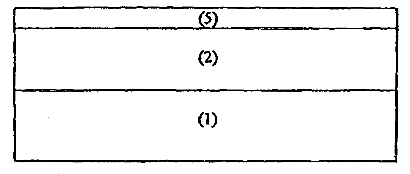
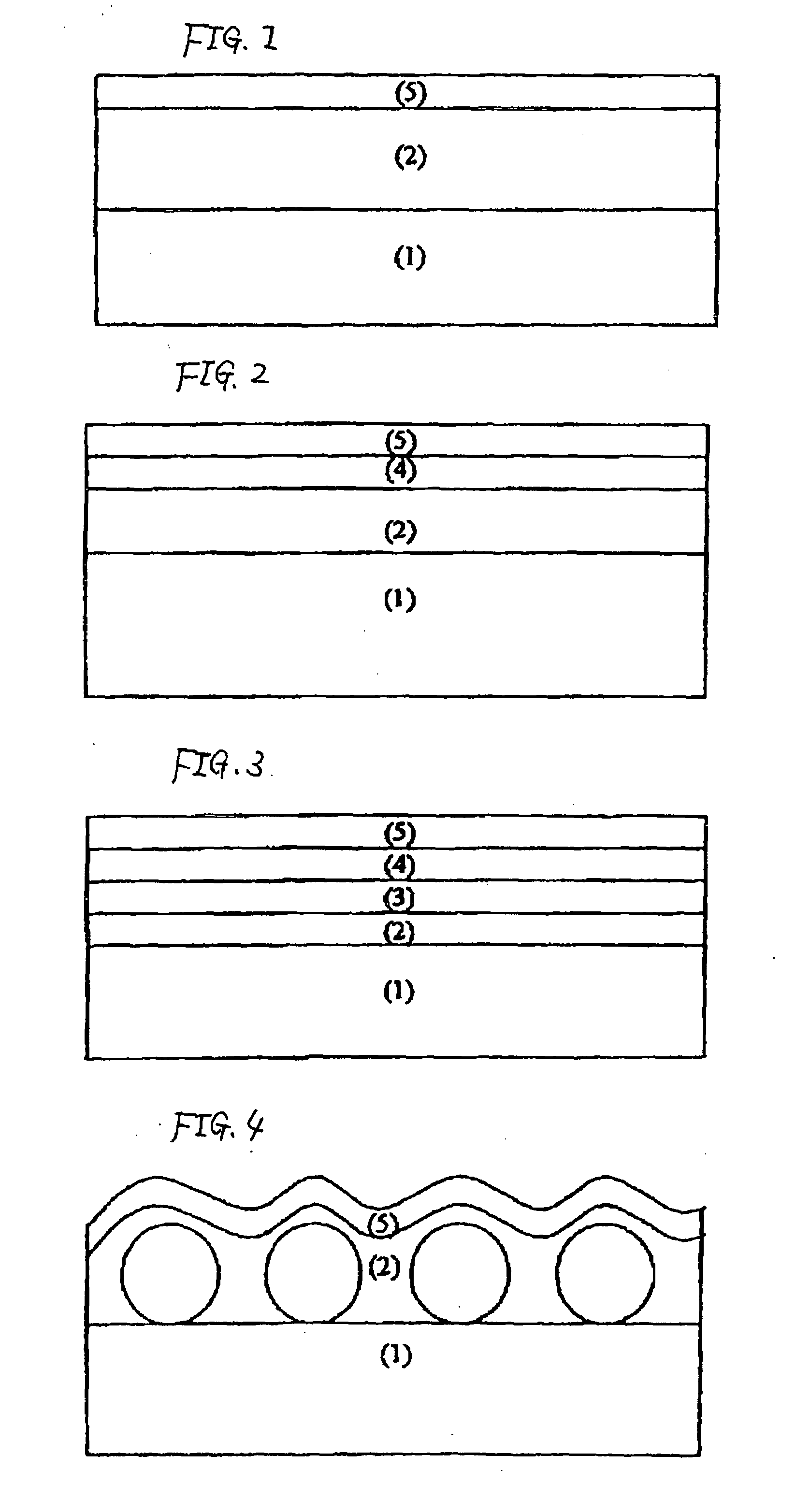
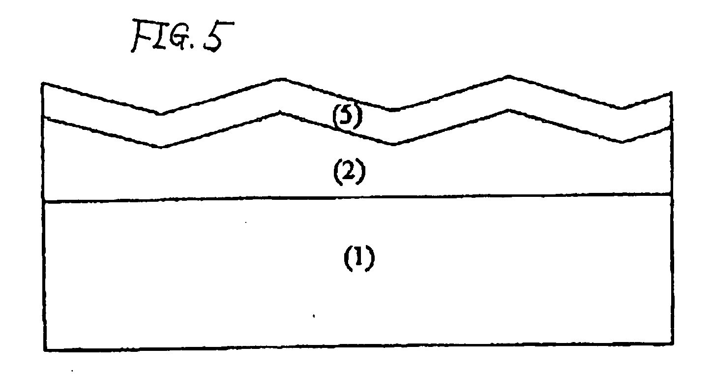
Image

Examples
example 19
[0511]A saponification solution prepared by keeping a 1.5 mol / L sodium hydroxide aqueous solution at 50° C. was prepared. Further, a 0.005 mol / L dilute sulfuric acid aqueous solution was prepared.
[0512]For each antireflection films manufactured in Examples 1 to 18, the surface of the transparent support opposite from the side having the low refractive index layer of the antireflection film was subjected to a saponification treatment by the use of the saponification solution. Then, the sodium hydroxide aqueous solution on the transparent support surface subjected to a saponification treatment was sufficiently washed with water, followed by washing with the dilute sulfuric acid aqueous solution. Further, the dilute sulfuric acid aqueous solution was sufficiently washed with water, and sufficiently dried at 100° C.
[0513]The contact angle to water of the surface of the transparent support on the side subjected to the saponification treatment of the antireflection film was evaluated and ...
example 20
[Manufacturing of Polarizing Plate]
[0517]As for an optical compensation film having an optical compensation layer “Wide View Film SA-12B”, {manufactured by Fuji Photo Film, Co., Ltd.}, the surface opposite from the side having the optical compensation layer was subjected to a saponification treatment under the same conditions as in Example 19.
[0518]For each polarizing film manufactured in Example 19, the saponification treated side of the antireflection film (protective film for a polarizing plate) manufactured in Examples 1 and 2 was each bonded to one side of the polarizing film using the same polyvinyl alcohol type adhesive as an adhesive. Further, to the other side of the polarizing film, the surface of the saponification treated optical compensation film opposite from the side having the optical compensation layer was bonded using the same polyvinyl alcohol type adhesive.
[Evaluation at Display Apparatus]
[0519]Each polarizing plate of Example 22 thus manufactured was mounted so ...
PUM
| Property | Measurement | Unit |
|---|---|---|
| wavelength | aaaaa | aaaaa |
| reflectance | aaaaa | aaaaa |
| thicknesses | aaaaa | aaaaa |
Abstract
Description
Claims
Application Information