Laser diode stack side-pumped solid state laser

a laser and diode stack technology, applied in lasers, laser cooling arrangements, laser details, etc., can solve the problems of critical heat dissipation, end-pumped lasers are typically of lower power than side-pumped lasers, and the gain medium is a large output power, so as to achieve good thermal coupling

Inactive Publication Date: 2007-09-20
NLIGHT PHOTONICS
View PDF38 Cites 19 Cited by
  • Summary
  • Abstract
  • Description
  • Claims
  • Application Information

AI Technical Summary

Benefits of technology

[0008] To provide package cooling, the laser diode stack is thermally coupled to a cooling block, the cooling block preferably including a slotted region into which the laser diode stack fits. In at least one preferred embodiment of the invention, thermally conductive and electrically isolating members are first bonded to the bottom and side surfaces of each submount and then bonded to the cooling block, the members being interposed between the laser diode stack and the cooling block. Preferably the cooling block is comprised of a pair of members, thus insuring good thermal coupling between the laser diode stack and the cooling block.

Problems solved by technology

End-pumped lasers are typically of lower power than side-pumped lasers due to the difficulty in coupling the output from multiple laser diodes into the relatively small end surface of the gain medium.
Although this approach may not optimize coupling efficiency, it typically results in greater output power from the gain medium due to the increased input energy.
Regardless of the configuration of the laser system, heat dissipation is a critical issue for several reasons.
First, heat build-up within the gain medium, especially in localized regions, can lead to instabilities in the output beam.
Second, heat build-up in the laser diode can lead to reduced operating efficiency, wavelength shifts and eventually catastrophic failure.
Third, both excessive temperature and thermal cycling can lead to component misalignment and in some instances, component de-bonding (for example, the cylindrical lenses attached to the output facets of the laser diodes in some configurations).
Heat dissipation systems, for example those that pump coolant through passages within the various system mounting structures, add significantly to system complexity, weight and cost, while not eliminating all of the issues that result from thermal cycling.

Method used


Image

  • Laser diode stack side-pumped solid state laser
  • Laser diode stack side-pumped solid state laser
  • Laser diode stack side-pumped solid state laser

Examples


Embodiment Construction

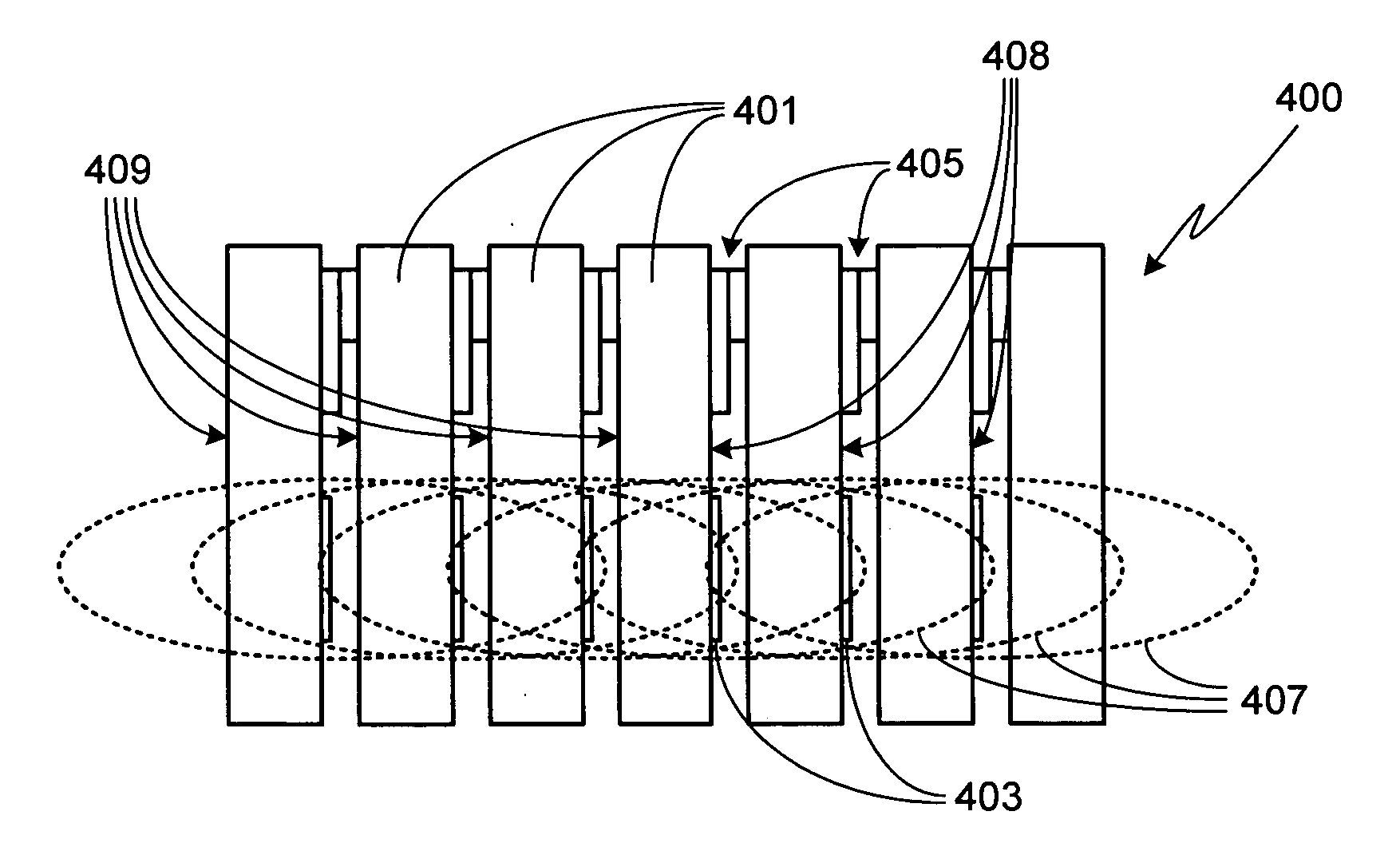
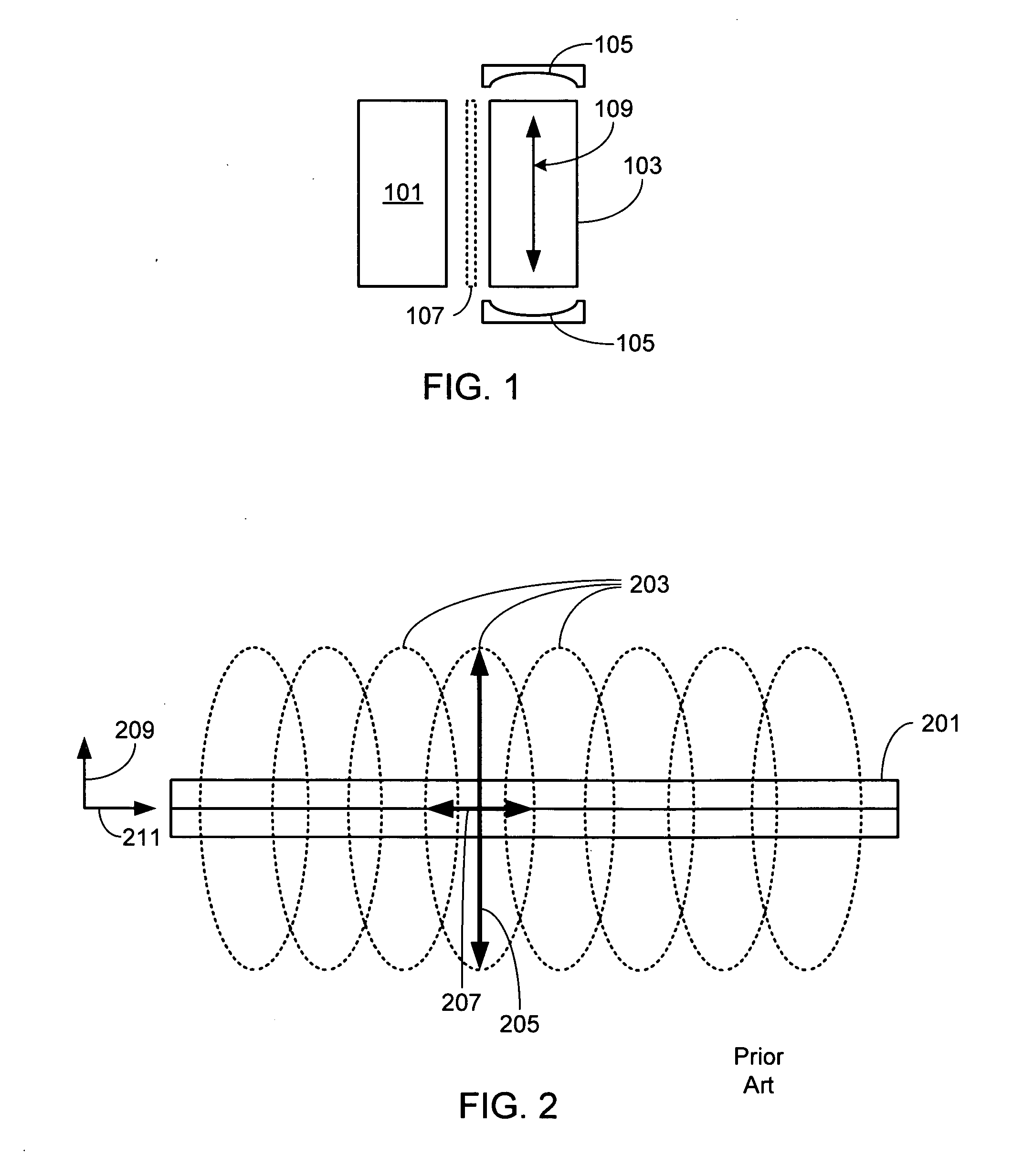
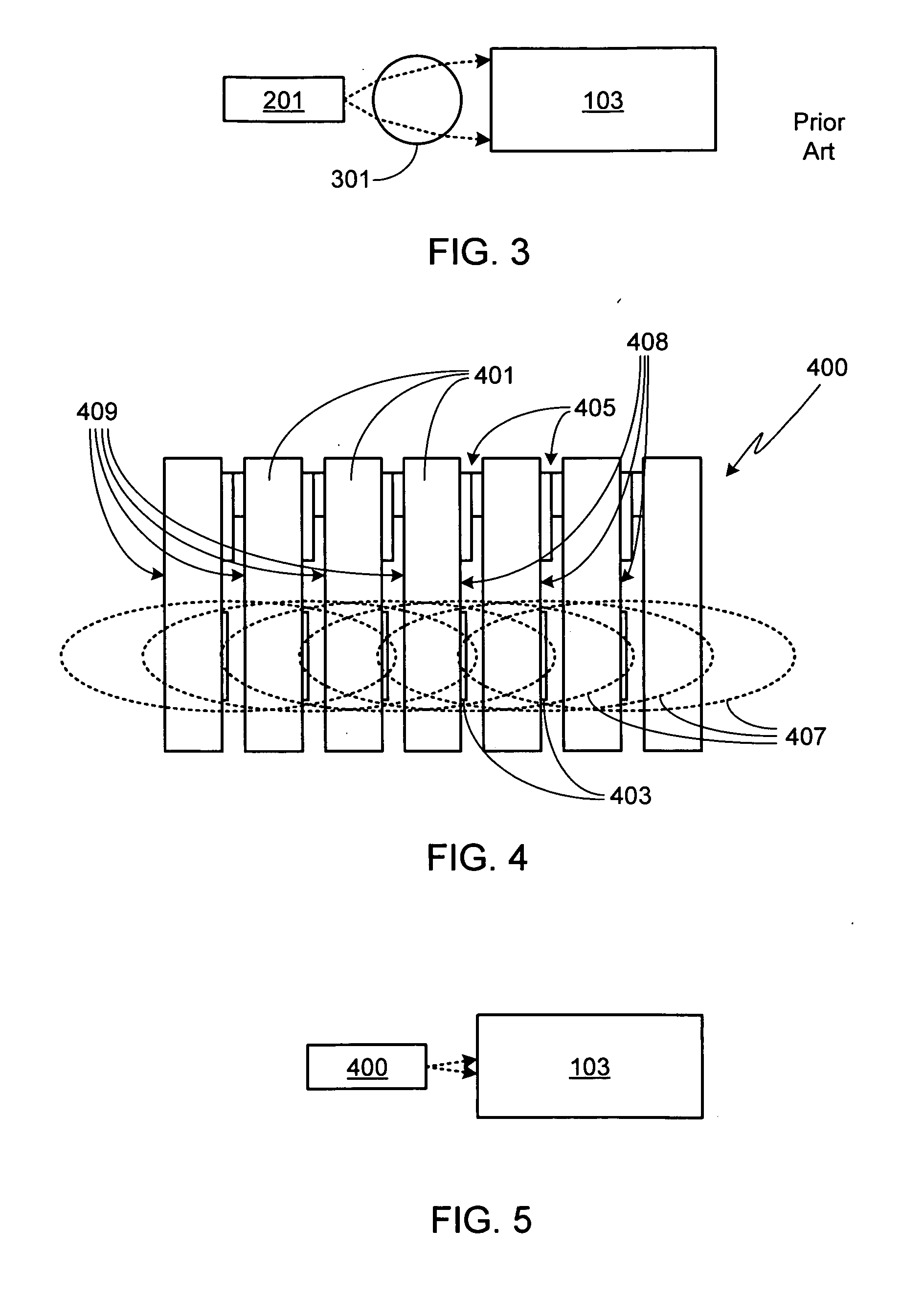
[0022]FIG. 1 is an illustration of a laser system in accordance with the invention. As shown, the system includes at least one laser diode stack 101, the laser gain medium 103, and laser cavity mirrors 105. It will be appreciated that the laser gain medium can be any appropriately doped glass or crystal of any shape, and that cylindrically-shaped (i.e., rod shaped) and rectangularly-shaped (i.e., slab shaped) medium are but two exemplary shapes. A variety of suitable materials, as well as a variety of suitable cavity configurations, are well know by those of skill in the art and will therefore not be described in detail herein. Although the system may include a coupling optic (e.g., a lens 107 shown in phantom) between laser diode stack 101 and laser gain medium 103, in the preferred embodiment there is no coupling optic as discussed in detail below.

[0023] In order to achieve the desired system performance, specifically increasing the solid angle of light collected by gain medium 1...


PUM


Abstract

A side-pumped solid state laser utilizing a laser diode stack of laser diode submount assemblies is provided. The laser gain medium of the solid state laser is contained within a laser cavity defined by a pair of reflective elements. Each laser diode submount assembly includes a submount to which one or more laser diodes are attached. The radiation-emitting active layer of each laser diode is positioned substantially parallel to the mounting surfaces of the submount, causing the fast axis of each laser diode's output beam to be substantially orthogonal to the submount mounting surfaces. The laser diodes can be of one wavelength or multiple wavelengths. Preferably the submount has a high thermal conductivity and a CTE that is matched to that of the laser diode. On top of the submount, adjacent to the laser diode, is a spacer. The laser diode stack is formed by mechanically coupling the bottom surface of each submount to the spacer of an adjacent submount assembly. Preferably the laser diode stack is thermally coupled to a cooling block.

Description

CROSS-REFERENCE TO RELATED APPLICATION [0001] This application is a continuation-in-part of U.S. patent application Ser. No. 11 / 384,940, filed Mar. 20, 2006, the disclosure of which is incorporated herein by reference for any and all purposes.FIELD OF THE INVENTION [0002] The present invention relates generally to semiconductor lasers and, more particularly, to a side-pumped solid state laser utilizing a laser diode stack as the pump source. BACKGROUND OF THE INVENTION [0003] High power laser diodes, due to their size, efficiency and wavelength range, are well suited for pumping high power solid state lasers. In such laser systems the output from one or more laser diodes is coupled into a laser gain medium, the gain medium contained within a laser cavity defined by a pair of mirrors or reflective coatings disposed at either end of the medium. The laser diode output may be coupled into either an end surface of the gain medium, creating an end-pumped laser, or into one or more side su...

Claims


Application Information

Patent Timeline
Patent Type & Authority Applications(United States)
IPC IPC(8): H01S3/04H01S5/00
CPCH01S5/02264H01S5/4025H01S5/024H01S5/02272H01S3/0941H01S5/02469H01S5/4087H01S3/061H01S5/02365H01S5/0237
Inventor DEFRANZA, MARKDAWSON, DAVIDFARMER, JASON
Owner NLIGHT PHOTONICS
Why Eureka
Try Eureka