Fuel Cell

a fuel cell and cell technology, applied in the field of fuel cells, can solve the problems of reducing the overall electricity generation efficiency of the system, lowering the fuel utilization efficiency, and reducing the product of the electricity generation efficiency of the stack and the fuel utilization efficiency, and achieve the effect of severely reducing the output density at the outer perimeter section

Inactive Publication Date: 2007-09-20
NISSAN MOTOR CO LTD
View PDF5 Cites 7 Cited by
  • Summary
  • Abstract
  • Description
  • Claims
  • Application Information

AI Technical Summary

Benefits of technology

[0005] In the fuel cell disclosed in the aforementioned publication, the fuel gas reacts as it flows from a circular disk-shaped center section toward an outer perimeter section. Consequently, the concentration of the hydrogen, hydrocarbon, or other electricity-generating fuel components in the fuel gas diminishes as the fuel gas moves from the center toward the out

Problems solved by technology

If an excessive quantity of fuel gas is supplied in an attempt to ensure that a sufficient amount of fuel gas is delivered to the outer perimeter section, the electricity generation efficiency of the stack will increase but the quantity of fuel gas that is discharged without being used for generating electricity will also increase, thus lowering the fuel utilization efficiency.
As a result, the overall electricity generation efficiency of the system, i.e., the product of the electricity generation efficiency of the stack and the fuel utilization

Method used


Image

  • Fuel Cell
  • Fuel Cell
  • Fuel Cell

Examples


first embodiment

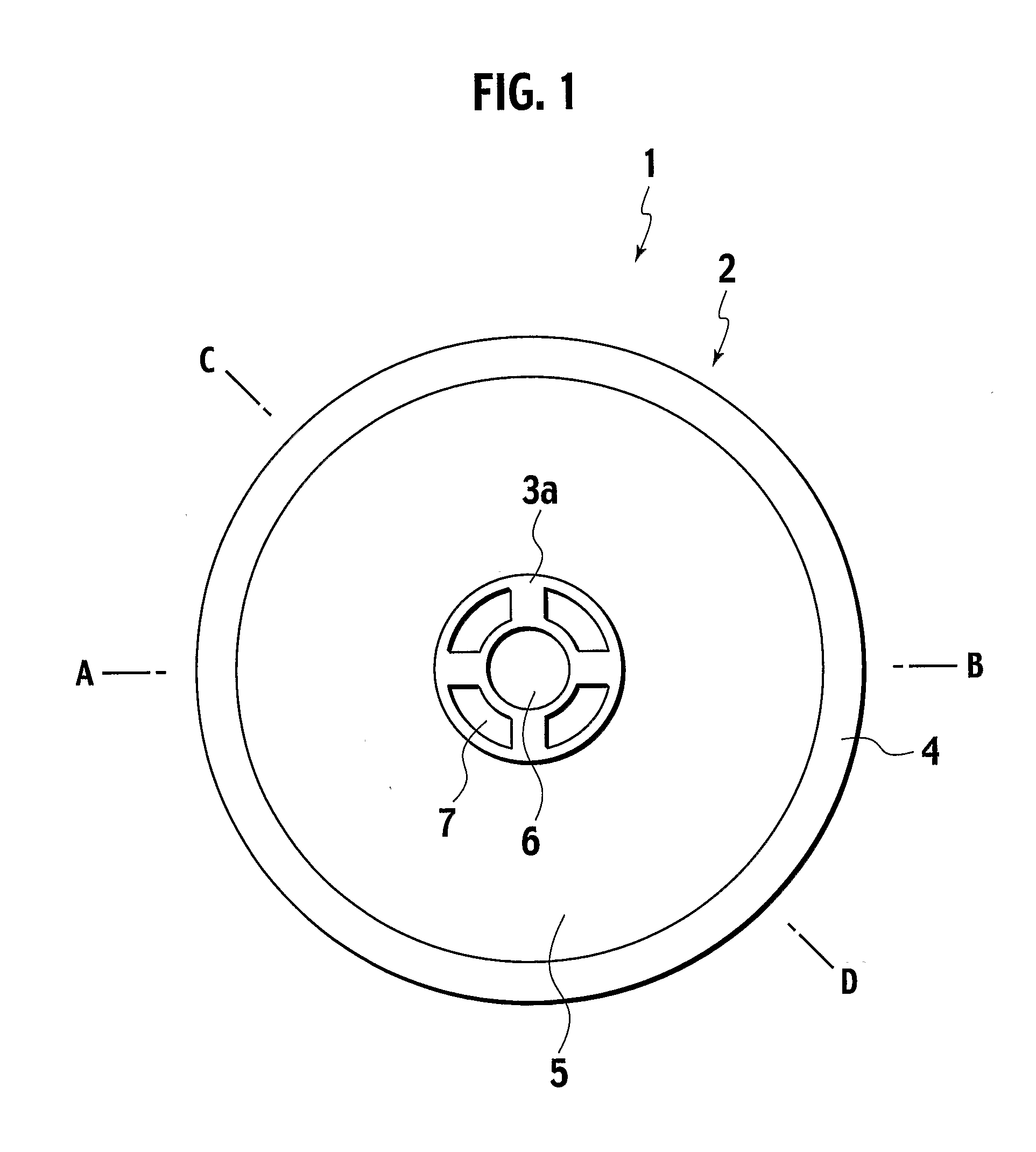
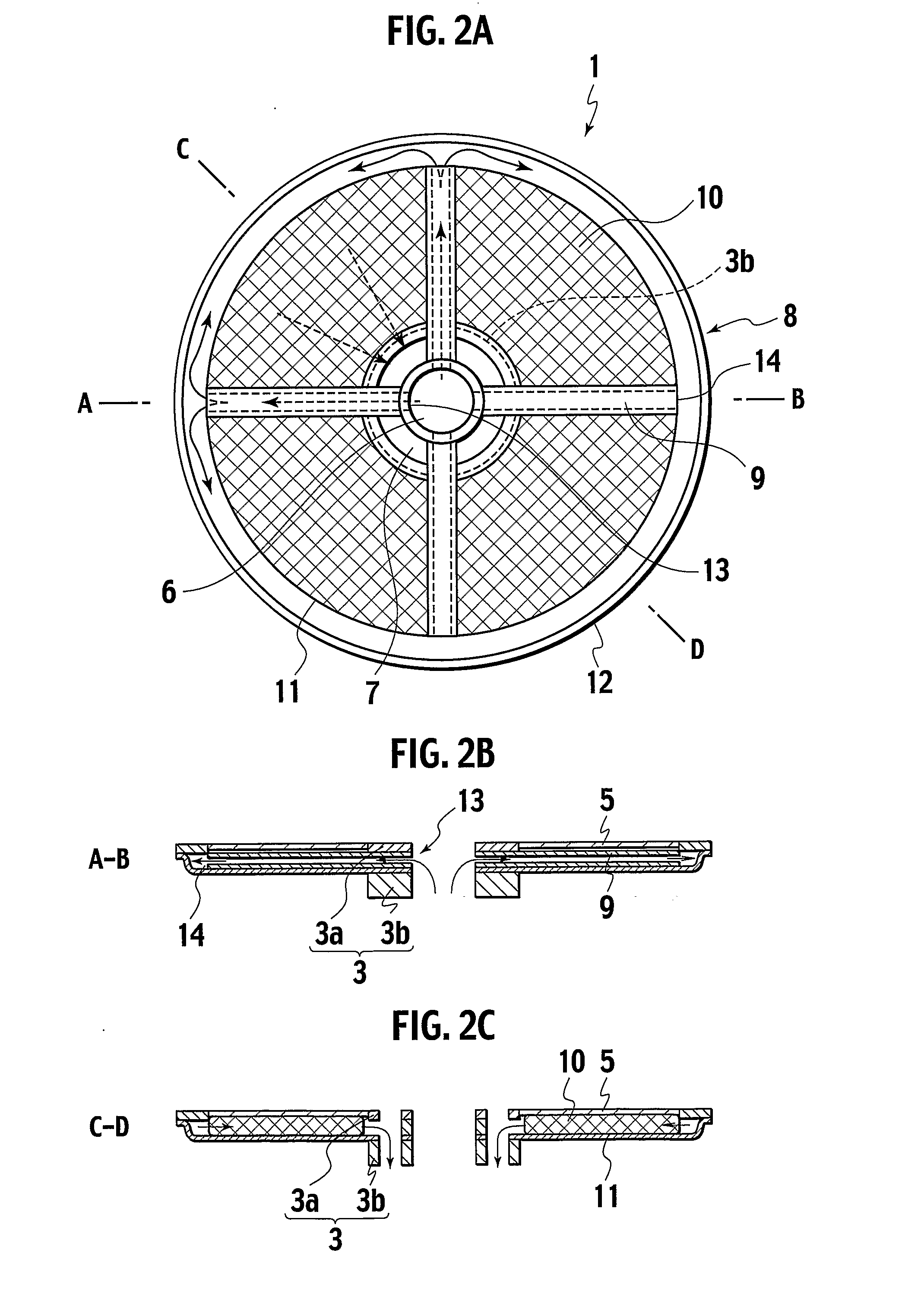
[0019]FIG. 1 is a plan view showing the hollow structural body of a fuel cell in accordance with the first embodiment. FIG. 2A is a plan view of the inside of the hollow structural body and FIGS. 2B and 2C are cross sectional views of the hollow structural body taken along section lines A-B and C-D, respectively. As shown in FIG. 1, the upper face of the hollow structural body 1 is made of a thin plate-like cell plate 2, and the cell plate 2 includes a metal cell plate manifold 3a, a metal outer rim section 4, and a donut-shaped electricity-generating cell 5 that are joined together.

[0020] The cell plate manifold 3a has a thickness of, for example, 1 millimeter and is provided with a gas introducing port 6 for introducing a fuel gas and a gas discharge port 7 for discharging the fuel gas. The electricity-generating cell 5 is an electrolyte support type cell and comprises a solid electrolyte layer, an oxidant electrode formed on one side of the solid electrolyte layer, and a fuel el...

second embodiment

[0043] A second embodiment of a fuel cell in accordance with the present invention will now be described with reference to FIGS. 5A, 5B, and 5C. FIG. 5A is a plan view showing the inside of a hollow structural body in accordance with this embodiment. FIGS. 5B and 5C are cross sectional views of the hollow structural body taken along section lines A-B and C-D. In the hollow structural body 51 of this embodiment, the rib flow passages 59 are different from the rib flow passages 9 of the first embodiment. Otherwise, the constituent features are the same as the first embodiment.

[0044] While the rib flow passages 9 of the first embodiment are configured to dispense the fuel gas in such a manner that the fuel gas hits the separator outer wall section 12 orthogonally, in this embodiment the rib flow passages 59 dispense the fuel gas in such a manner that the fuel gas hits the separator outer wall section 12 at a slanted angle.

[0045] Thus, in a fuel cell in accordance with the second embo...

third embodiment

[0046] A third embodiment of a fuel cell in accordance with the present invention will now be described with reference to FIGS. 6A, 6B, and 6C. FIG. 6A is a plan view showing the inside of a hollow structural body in accordance with this embodiment. FIGS. 6B and 6C are cross sectional views of the hollow structural body taken along section lines A-B and C-D. In the hollow structural body 61 of this embodiment, the dispensing holes 62 of the rib flow passages 69 are different and the fact that the separator manifold 3a is provided with an outer ring 63 is different. Otherwise, the constituent features are the same as the first embodiment.

[0047] The separator manifold 3a of this embodiment is provided with an outer ring 63. The outer ring 63 makes it possible to support the manifold 3 on the bottom of the hollow structural body 1, to support the rib flow passage 69, to improve the quality of the diffusion bond, and to prevent warping.

[0048] The rib flow passages 69 of this embodimen...


PUM


Abstract

An aspect of the present invention provides a fuel cell that includes, hollow structural bodies each provided with an internal space for reacting a fuel gas and an oxidant gas, each hollow structural body including, a separator having a perimeter wall section that follows along a rim, a cell plate having an electricity-generating cell having its outer perimeter joined to the separator such that a space for a gas to flow through is formed between the separator and the cell plate, a gas supply manifold to supply one of the reactant gases, a gas discharge manifold to discharge the reactant gas, and a gas introducing flow passage to introduce said reactant gas from the gas supply manifold to the perimeter wall section of the separator, wherein the reactant gas introduced into the gas introducing passage flows from the vicinity of the perimeter wall section of the separator to the gas discharge manifold.

Description

TECHNICAL FIELD [0001] The present invention relates to a fuel cell. More specifically, the present invention relates to a solid oxide fuel cell configured to generate electricity by conducting an electrochemical reaction between a fuel gas and an oxidant gas through a solid oxide electrolyte. BACKGROUND ART [0002] In a fuel cell, hydrogen gas or other fuel gas and an oxidant gas containing oxygen are separated by an electrolyte disposed there-between and reacted with each other electrochemically through the electrolyte. Electric energy is extracted directly from electrodes provided on both sides of the electrolyte. Fuel cells are classified based on the type of electrolytic material used. Examples of the main types include phosphoric acid fuel cells (PAFC), molten carbonate fuel cells (MCFC), solid oxide fuel cells (SOFC), and solid polymer fuel cells (PECF). [0003] Solid oxide fuel cells are easy to handle because they use a solid oxide material that is conductive with respect to ...

Claims


Application Information

Patent Timeline
IPC IPC(8): H01M8/02H01M8/24H01M8/04H01M8/12
CPCH01M8/0247H01M8/04089Y02E60/525H01M8/2425Y02E60/521H01M8/1206H01M8/1231Y02E60/50H01M8/2432H01M8/2484H01M8/243
Inventor KUSHIBIKI, KEIKOSATOU, FUMINORIHARA, NAOKINAKAJIMA, YASUSHIIBUKA, SHIGEO
Owner NISSAN MOTOR CO LTD
Why Eureka
Try Eureka