Semiconductor-processing apparatus with rotating susceptor

a susceptor and semiconductor technology, applied in chemical vapor deposition coating, coating, metallic material coating process, etc., can solve the problems of inability to use mass flow control and other conventional flow control methods, inability to monitor process on time, and difficulty in controlling film thickness on the molecular layer level

Inactive Publication Date: 2007-09-20
ASM JAPAN
View PDF48 Cites 298 Cited by
  • Summary
  • Abstract
  • Description
  • Claims
  • Application Information

AI Technical Summary

Benefits of technology

[0010]Consequently, in an aspect, an object of the present invention is to provide an apparatus which can solve one or more of the above problems. In an embodiment, the apparatus for depositing thin film on a processing target such as a semiconductor wafer comprises: a reaction chamber; a susceptor for placing multiple processing targets thereon which is movable up and down and rotatable around its center axis; and isolation walls that divide the reaction chamber into multiple chambers (compartments) including source gas chambers and purge gas chambers, wherein when the susceptor is raised for film deposition, a small gap is created between the susceptor and the isolation walls, thereby establishing gaseous separation between the respective chambers, wherein each source gas chamber and each purge gas chamber are provided alternately in a susceptor-rotating direction of the susceptor. The susceptor on which the multiple targets are placed is rotated while continuously alternating the steps of adsorption of source gas A, purge, reaction of adsorbed source gas A with source gas B, and purge, so as to deposit thin film on each target.

Problems solved by technology

Furthermore, mass-flow control and other conventional flow control means cannot be used because of the requirement for high-speed gas switching, which inhibits on-time process monitoring.
If gas remains inside the reactor, CVD reaction occurs in the vapor phase, which in turn makes it difficult to control film thickness on the molecular layer level.
Also, reaction in the vapor phase generates larger grains that become unwanted particles.
Traditionally, a long purge time has been required to completely discharge remaining gas A or B from the reactor, which reduces productivity.
However, this method requires that the interior of showerheads that are shared by precursors A and B and thus having a lot of dead space be purged for a long period.
In this case, however, division by means of gas curtains cannot prevent the chemical reaction between precursors A and B that are positioned side by side, and particles generate as a result.
Another problem presented by conventional methods is the need for high-speed, repeated on / off switching of RF plasma under PEALD, where the on period must be at least one second long, or preferably two seconds, in order to stabilize plasma.
However, in some cases, they may not provide sufficient effectiveness.

Method used


Image

  • Semiconductor-processing apparatus with rotating susceptor
  • Semiconductor-processing apparatus with rotating susceptor
  • Semiconductor-processing apparatus with rotating susceptor

Examples


example 1

[0124]Shown below are the film deposition results of the method according to an embodiment of the present invention and a conventional method, in an example of WNC (tungsten nitride carbide) film deposition using TEB (triethyl boron), WF6 (tungsten hexafluoride), NH3 (ammonia) as precursors, and Ar as purge gas or inert gas. For the embodiment of the present invention, an apparatus shown in FIGS. 8, 17, and 24 were used wherein:

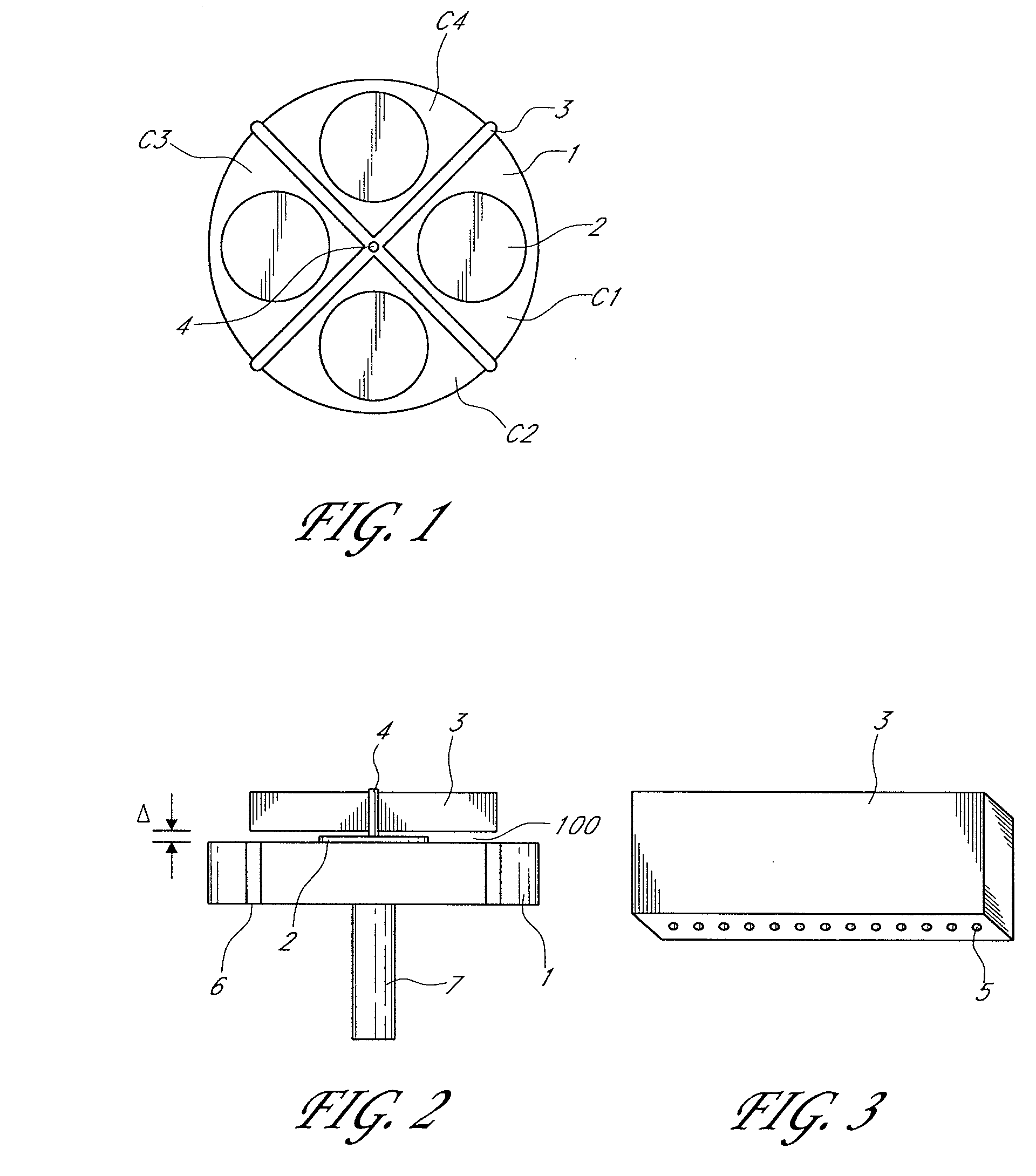
[0125]The gap Δ: 1.2 mm

[0126]The height α+β of the isolation wall: 51.5 mm

[0127]The thickness β of the top plate: 50 mm

[0128]The width of the cutout: 10 mm

[0129]The peripheral angle of the purge gas compartment: 20°

[0130]The peripheral angle of the reaction gas compartment: 30°

[0131]The number of outflow holes for purge gas and reaction gas: 50

[0132]The diameter of the wafer: 300 mm

[0133]The flow of purge gas from the center: 20 sccm

[0134]The flow of purge gas to the compartments: 1000 sccm

[0135]The flow of precursor TEB: 400 sccm with carrier N2 gas

[0136]The...

example 2

[0147]Explained below is an example of Ru film deposition by PEALD (plasma enhance ALD) according to an embodiment of the present invention. For this embodiment of the present invention, simulation was conducted to calculate a throughput assuming that an apparatus shown in FIGS. 9, 13, and 26 are used wherein conditions not specified below are the same as in Example 1:

[0148]The peripheral angle of the purge gas compartment: 15°

[0149]The peripheral angle of the reaction gas compartment: 20°

[0150]The peripheral angle of the RFA compartment: 90°

[0151]RF power: 200 W, 13.56 MHz

[0152]The flow of purge gas from the center: 20 sccm

[0153]The flow of purge gas to the compartments: 1000 sccm

[0154]The flow of precursor Ru: 400 sccm with He carrier gas

[0155]The flow of precursor NH3: 400 sccm

[0156]The pressure of the compartments P1-P2: 200 Pa

[0157]The pressure of the compartments R1: 400 Pa

[0158]The pressure of the compartment RFA: 150 Pa

[0159]The temperature of the reaction chamber (depositio...


PUM

PropertyMeasurementUnit
decomposition temperaturesaaaaaaaaaa
temperatureaaaaaaaaaa
angleaaaaaaaaaa

Abstract

An apparatus for depositing thin film on a processing target includes: a reaction space; a susceptor movable up and down and rotatable around its center axis; and isolation walls that divide the reaction space into multiple compartments including source gas compartments and purge gas compartments, wherein when the susceptor is raised for film deposition, a small gap is created between the susceptor and the isolation walls, thereby establishing gaseous separation between the respective compartments, wherein each source gas compartment and each purge gas compartment are provided alternately in a susceptor-rotating direction of the susceptor.

Description

CROSS-REFERENCE TO RELATED APPLICATIONS[0001]This is a continuation-in-part of U.S. patent application Ser. No. 11 / 376,048, filed Mar. 15, 2006, the disclosure of which is incorporated herein by reference in its entirety.BACKGROUND OF THE INVENTION[0002]1. Field of the Invention[0003]The present invention generally relates to a film deposition apparatus and method for depositing thin film by atomic layer chemical vapor deposition (ALCVD), for example, on a processing target such as a semiconductor wafer.[0004]2. Description of the Related Art[0005]In line with the growing needs for semiconductor apparatuses capable of handling more highly integrated circuits, the ALCVD (atomic layer CVD) method, which achieves better controllability for thin film deposition than the conventional CVD (chemical vapor deposition) method, is drawing the attention. Prior technologies in this field include U.S. Pat. No. 6,572,705, U.S. Pat. No. 6,652,924, U.S. Pat. No. 6,764,546, and U.S. Pat. No. 6,645,5...

Claims


Application Information

Patent Timeline
Patent Type & Authority Applications(United States)
IPC IPC(8): C23C16/00H01L21/31
CPCC23C16/06C23C16/36H01L21/68764H01L21/67161H01L21/67748C23C16/45551H01L21/20
Inventor SHIMIZU, AKIRAKOH, WONYONGPARK, HYUNG-SANGTAK, YOUNG-DUCK
Owner ASM JAPAN
Why Eureka
Try Eureka