Apparatus, system, and method for regenerating an exhaust gas treatment device

a technology of exhaust gas treatment and equipment, applied in the direction of mechanical equipment, engines, machines/engines, etc., can solve the problems of increasing the cost of operating the engine, and achieve the effects of reducing nox emissions, reducing reductants, and reducing exhaust gas emissions

Active Publication Date: 2007-09-27
CUMMINS FILTRATION INC
View PDF27 Cites 23 Cited by
  • Summary
  • Abstract
  • Description
  • Claims
  • Application Information

AI Technical Summary

Benefits of technology

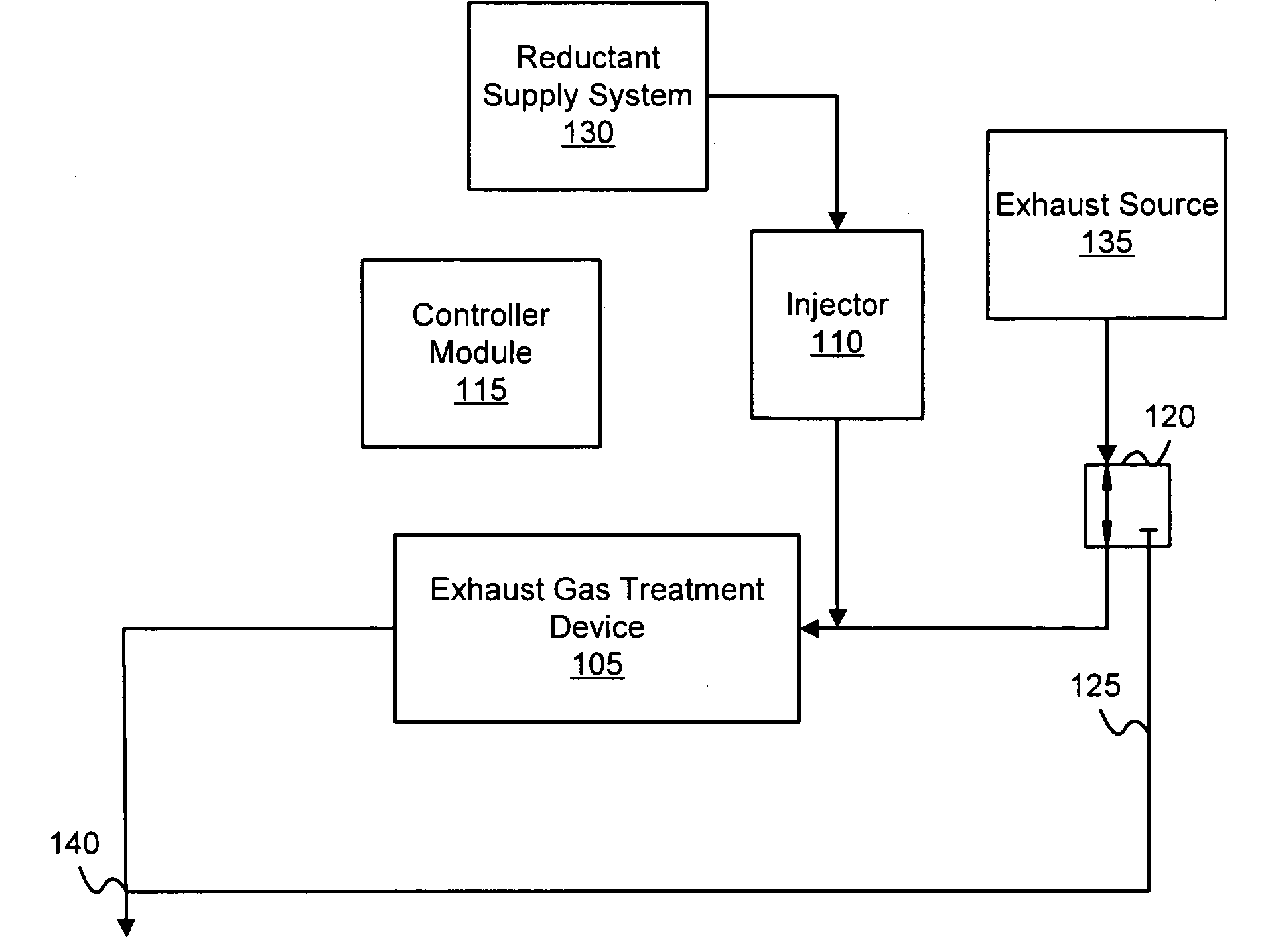
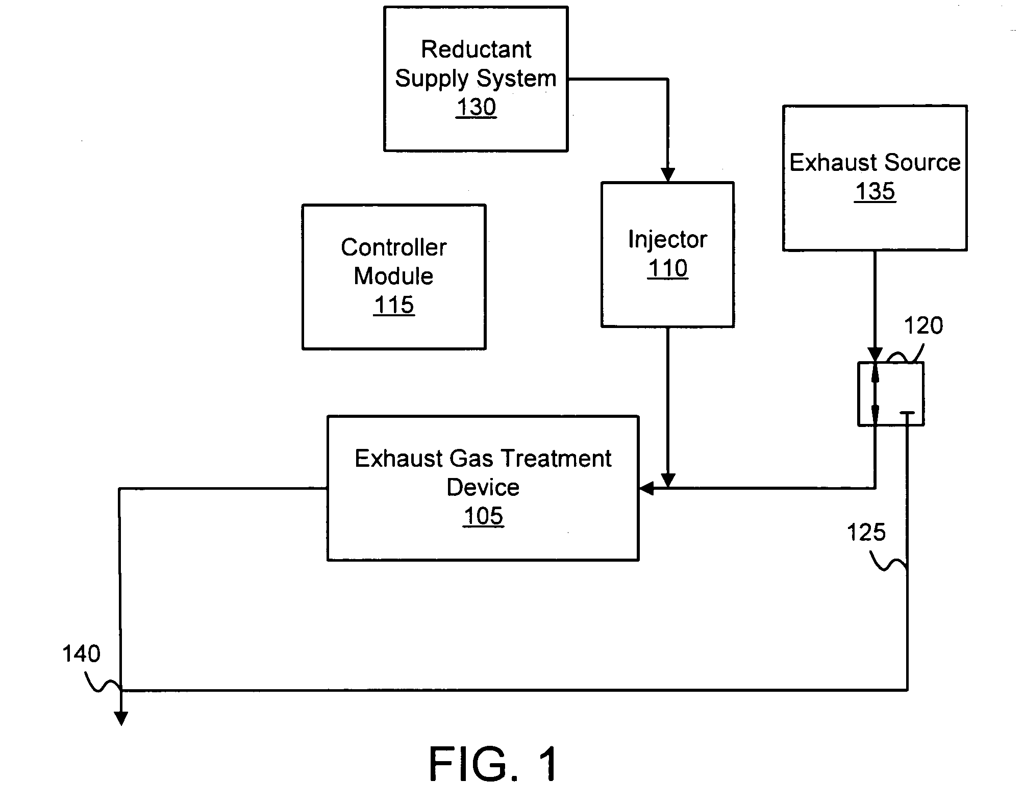
[0015]The internal combustion engine oxidizes a hydrocarbon-based fuel such as diesel fuel to create mechanical energy. In addition, the internal combustion engine creates an exhaust gas that includes emissions. The emissions may include NOX. The exhaust gas treatment device reduces the emissions from the exhaust gas. In one embodiment, the exhaust gas treatment device adsorbs NOX as nitrates to reduce NOX emissions.
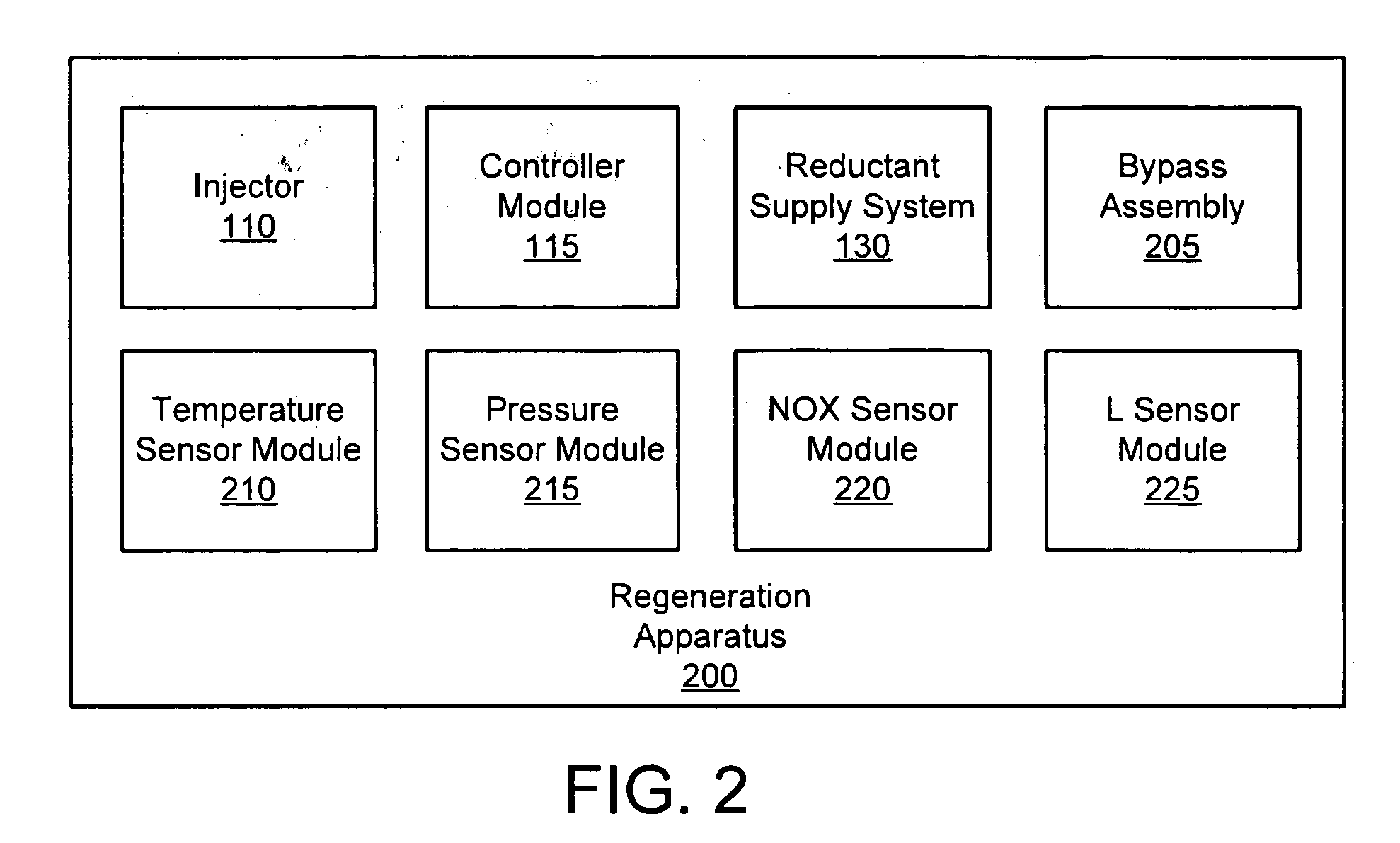
[0016]The injector provides reductant to the exhaust gas treatment device to regenerate the exhaust gas treatment device. In one embodiment, the reductant drives adsorbed nitrates from the exhaust gas treatment device. The controller module directs the injector to provide the reductant over a plurality of rich intervals during a regeneration cycle. In addition, the controller module directs the injector to reduce the reductant provided over a lean interval between the rich intervals. The system regenerates the exhaust gas treatment device with reduced reductant and further reduces hydrocarbon slip during regeneration.

Problems solved by technology

Unfortunately, injecting the reductant into the exhaust gas to regenerate the exhaust gas treatment device consumes reductant, increasing the cost of operating the engine.

Method used


Image

  • Apparatus, system, and method for regenerating an exhaust gas treatment device
  • Apparatus, system, and method for regenerating an exhaust gas treatment device
  • Apparatus, system, and method for regenerating an exhaust gas treatment device

Examples


Embodiment Construction

[0035]Many of the functional units described in this specification have been labeled as modules, in order to more particularly emphasize their implementation independence. For example, a module may be implemented as a hardware circuit comprising custom very large scale integration (“VLSI”) circuits or gate arrays, off-the-shelf semiconductors such as logic chips, transistors, or other discrete components. A module may also be implemented in programmable hardware devices such as field programmable gate arrays, programmable array logic, programmable logic devices or the like.

[0036]Modules may also be implemented in software for execution by various types of processors. An identified module of executable code may, for instance, comprise one or more physical or logical blocks of computer instructions, which may, for instance, be organized as an object, procedure, or function. Nevertheless, the executables of an identified module need not be physically located together, but may comprise ...


PUM


Abstract

An apparatus, system, and method are disclosed for regenerating an exhaust gas treatment device. A controller module directs an injector to provide reductant to an exhaust gas treatment device over a plurality of rich intervals during a regeneration cycle. In addition, the controller module directs the injector to reduce the reductant provided to the exhaust gas treatment device over a lean interval between the rich intervals to create a lean environment within the exhaust gas treatment device. In one embodiment, the controller module modifies the reductant provided during each rich interval, the number of rich intervals, the length of the rich intervals, and the length of the lean intervals in response to an exhaust gas state.

Description

BACKGROUND OF THE INVENTION[0001]1. Field of the Invention[0002]This invention relates to regenerating an exhaust gas treatment device and more particularly relates to regenerating the exhaust gas treatment device with reduced reductant and hydrocarbon slip.[0003]2. Description of the Related Art[0004]Engines that derive energy from combustion such as internal combustion engines produce an exhaust gas. The exhaust gas may include one or more undesirable emissions (hereinafter emissions) such as nitrogen oxide (“NOX”), carbon monoxide, and the like. Internal combustion engines such as diesel engines, gasoline engines, and the like often have exhaust systems with exhaust gas treatment devices such as catalytic converters to remove emissions from exhaust gas.[0005]In one embodiment, a catalytic converter may be a NOX adsorber. The NOX adsorber adsorbes NOX from the exhaust gas onto a site of the NOX adsorber by oxidizing the NOX to create a nitrate. The nitrate remains on the NOX adsor...

Claims


Application Information

Patent Timeline
Patent Type & Authority Applications(United States)
IPC IPC(8): F01N3/00
CPCF01N3/0253F01N13/009F01N3/0842F01N3/0878F01N3/0885F01N3/2033F01N9/00F01N11/002F01N2560/023F01N2560/026F01N2560/06F01N2560/08Y02T10/26Y02T10/47F01N3/035Y02T10/12Y02T10/40
Inventor CUNNINGHAM, MICHAELSTROIA, BRADLEE
Owner CUMMINS FILTRATION INC
Why Eureka
Try Eureka