Heating device

a heating device and heat sink technology, applied in the field of heating devices, can solve the problems of increasing the risk of cracking, and the thin dielectric material layer or the insulating material layer may have a crack, so as to prevent the tensile strength of the brazing joint section from being reduced, the brazing area is sufficient, and the strength is sufficient.

Active Publication Date: 2007-09-27
NGK INSULATORS LTD
View PDF2 Cites 5 Cited by
  • Summary
  • Abstract
  • Description
  • Claims
  • Application Information

AI Technical Summary

Benefits of technology

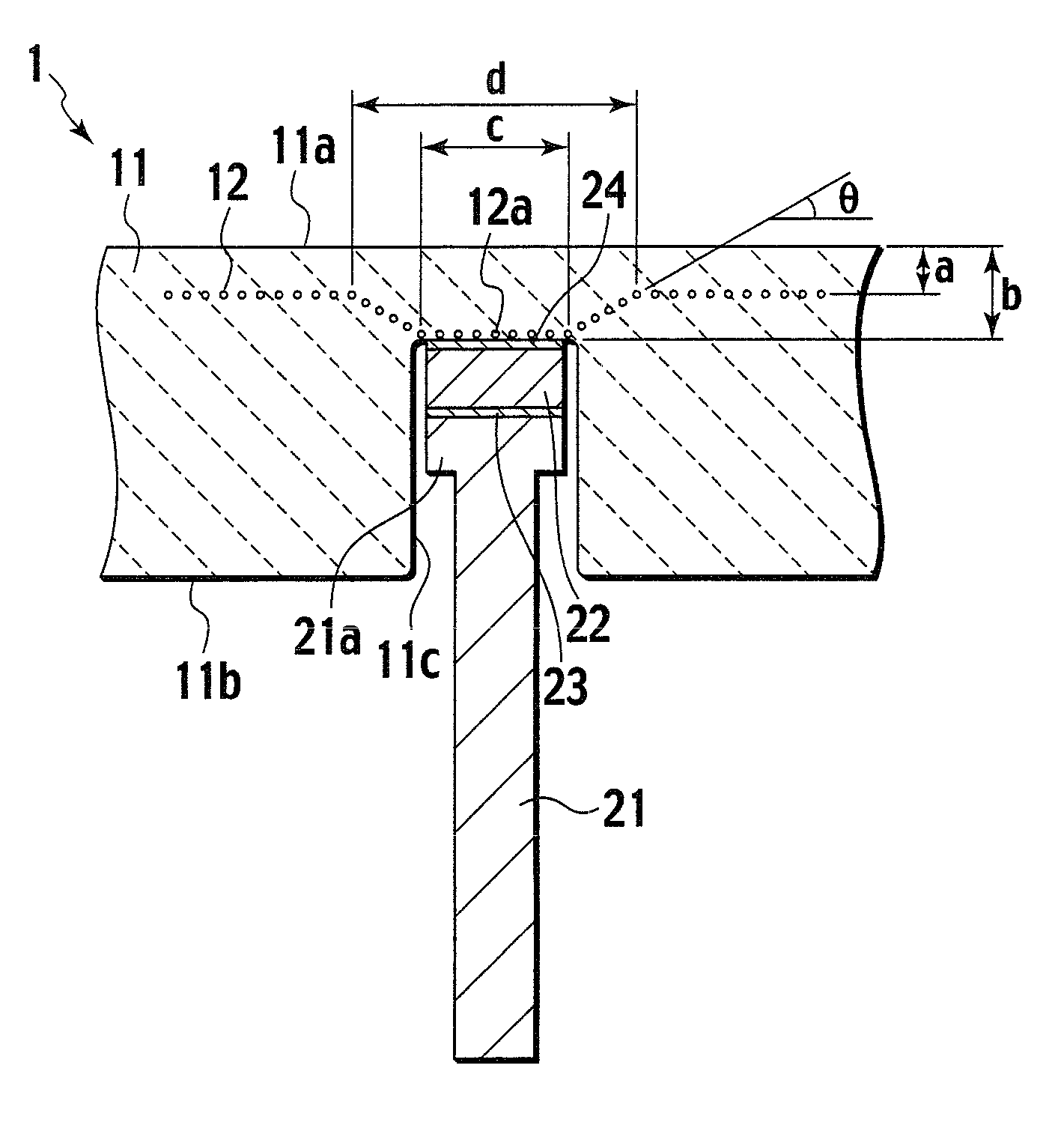
[0036]The trapezoidal cone-like shape of the concave section 12a of the high-frequency electrode 12 is more preferably structured so that a bottom face of a trapezoidal cone-like concave section has a diameter (the reference numeral “c” of FIG. 1) of 3 mm or more and 5 mm or less, the depth of the concave section (a difference between the distance “b” and the distance “a” of FIG. 1) is 1 mm or more and 3 mm or less, the concave section has the maximum diameter (the reference numeral “d” of FIG. 1) of 7 mm or less, and the inclination angle of the side wall of the concave section (the reference numeral θ of FIG. 1) is larger than 30° and satisfies 75°. When these numeric ranges are satisfied, a particularly sufficient strength can be obtained. The diameter of the bottom face of the trapezoidal cone-like concave section (the reference numeral “c” of FIG. 1) of 3 mm or more and 5 mm or less in particular can secure a sufficient brazing area. Thus, an effect is obtained according to which the tensile strength of a brazing joint section is prevented from being reduced, which is preferable. Furthermore, the inclination angle of the side wall of the concave section (the reference numeral θ of FIG. 1) larger than 30° and satisfying 75° can disperse in a circular manner the thrust applied to the high-frequency electrode for example so that a dielectric material layer or an insulating material layer in a wide region as seen from the heating surface 11a can support the load such as thrust.
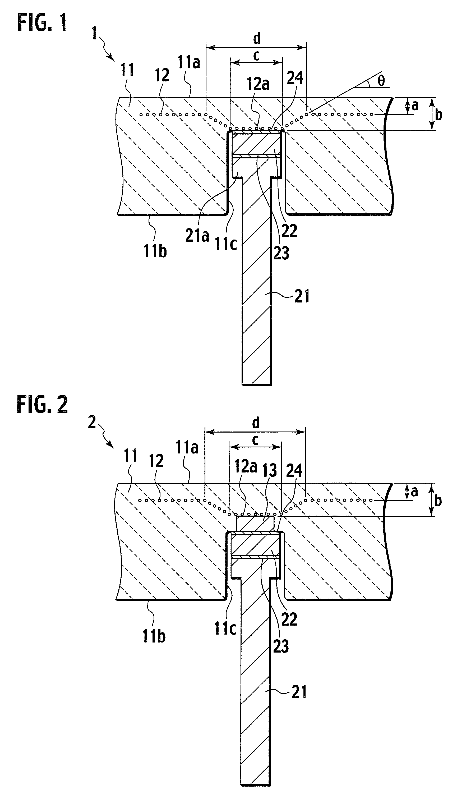
[0037]Next, FIG. 2 is a cross-sectional view illustrating the main part of another illustrative embodiment of the present invention. It is noted that the same members in FIG. 2 as those of FIG. 1 are denoted with the same reference numerals and thus will not be described further.
[0038]A heating device 2 shown in FIG. 2 is the same as the heating device 1 shown in FIG. 1 in which the mesh-like high frequency electrode 12 embedded in the ceramics base 11 has the trapezoidal cone-like concave section 12a to this conducting hole 11c at a position of the ceramics base 11 opposed to the conducting hole 11c. The bottom section of this trapezoidal cone-like concave section 12a is connected to a conductive member 13 embedded between this trapezoidal cone-like concave section 12a and the bottom face of the conducting hole 11c of the ceramics base 11. This conductive member 13 is made of the same sintered Mo metal as that of the high-frequency electrode 12. A surface of this conductive member 13 opposed to this conducting hole 11c is exposed in this penetration hole 11a and this surface is fixedly brazed to the stress relaxation material 22 at the tip end of the power feeding material 21 by gold brazing material 24.
[0039]The illustrative embodiment shown in FIG. 2 provides the same effect as that by the illustrative embodiment shown in FIG. 1. Thus, the region as the insulating material layer between this high-frequency electrode 12 and the heating surface 11a can have an increased strength, thus suppressing the generation of a crack. Furthermore, the high-frequency electrode 12 does not have any adverse affects on the distribution of densities of plasma generated on the heating surface 11a of the ceramics base 11.
[0040]The illustrative embodiment shown in FIG. 2 also provides the concave section 12a of the high-frequency electrode 12 with a trapezoidal cone-like shape. Thus, the same effect as that described in the illustrative embodiment shown in FIG. 1 can be obtained. Furthermore, a more preferable numeric range of the trapezoidal cone-like shape of the concave section 12a of the high-frequency electrode 12 shown in FIG. 2 is the same numeric range as that described in the illustrative embodiment shown in FIG. 1.
[0041]Next, FIG. 3 and FIG. 4 are a cross-sectional view illustrating the main part of a conventional heating device as a comparative example. In FIG. 3 and FIG. 4, the same members as those of FIG. 1 and FIG. 2 are denoted with the same reference numerals and will not be described further.

Problems solved by technology

This has caused a risk where this thin dielectric material layer or an insulating material layer may have a crack when a region as a dielectric material layer between this high-frequency electrode and the heating surface that is opposed to the hole inserted with the power feeding material is subjected to a thrust for inserting the Ni rod made of this power feeding material to the hole or when this Ni rod is expands or contracts.
This has caused a risk where this thrust may cause a crack.
This repeated stress also causes a risk of a crack.
Thus, the condition of the heating surface gradually deteriorates after the use for a long period of time.
This gradual deterioration causes increased cracks even when a load that is caused by the above-described thrust or repeated stress and that is applied to the thin dielectric material layer is fixed.
This has caused a risk of a shorter life after the use for a long period of time.
Once such a crack is caused, the crack grows due to the presence of the above described pressure difference, plasma or corrosive environment, and the grown crack penetrates the dielectric material layer, causing the heater, the electrostatic chuck, or the susceptor to be nonusable.

Method used


Image

  • Heating device
  • Heating device
  • Heating device

Examples


examples

[0052]The heating devices as shown in FIG. 1 and FIG. 2 were prepared. First, a ceramics base was prepared in the manner as described below. First, AIN powders obtained by the reduction-nitridation method were added with 5% of Y2O3 to provide ceramics mixed powders. Then, the ceramics mixed powders were added with acrylic resin binder to prepare granulated powders by the spraying granulation method. The granulated powders were filled in a metal mold and were pressed to prepare a preparatory compact. Then, a transfer pattern was used to form a groove at a position at which a resistance heating element is embedded. Then, the groove includes therein a linear Mo resistance heating element that is provided as a wound body having a diameter of 0.5 mm. Then, ceramics raw material powders are filled in this grooved. Then, an alumina-made bulk component having the same shape as that of the inner side of this concave section was placed at a part corresponding to the concave section of the hig...


PUM

PropertyMeasurementUnit
distanceaaaaaaaaaa
diameteraaaaaaaaaa
depthaaaaaaaaaa

Abstract

A heating device includes a high-frequency electrode embedded substantially in parallel with a heating surface of a ceramics base in the vicinity of the heating surface. A conducting hole toward this high-frequency electrode is formed in a back face of the ceramics base. This high-frequency electrode has a trapezoidal cone-like concave section toward the conducting hole at a region opposed to the conducting hole.

Description

CROSS-REFERENCE TO RELATED APPLICATION[0001]This application is based upon and claims the benefit of priority from Patent Application No. 2006-84104 filed on Mar. 24, 2006, in the Japanese Patent Office, of which the contents are incorporated herein by reference.BACKGROUND OF THE INVENTION[0002]1. Field of the Invention[0003]The present invention relates to a heating device.[0004]2. Description of Related Art[0005]In a step for manufacturing a semiconductor device, a wafer is heated for forming an oxide film on the wafer by a semiconductor manufacture apparatus. One of heating devices in this semiconductor manufacture apparatus for heating a wafer is structured so that a resistance heating element is embedded in a disk-like ceramics base on which a wafer as a to-be-heated object is placed and is heated. This heating device is advantageously adapted not only to a film formation apparatus used for a semiconductor manufacture process but also to a surface processing apparatus such as a...

Claims


Application Information

Patent Timeline
Patent Type & Authority Applications(United States)
IPC IPC(8): H05B3/44
CPCH05B3/143H01L21/67103
Inventor NISHIOKA, MASAO
Owner NGK INSULATORS LTD
Why Eureka
Try Eureka