Plasma processing apparatus

Inactive Publication Date: 2007-10-04
TOKYO ELECTRON LTD
View PDF13 Cites 30 Cited by
  • Summary
  • Abstract
  • Description
  • Claims
  • Application Information

AI Technical Summary

Benefits of technology

[0016] Further, it is also preferable that a gas chamber for introducing a processing gas from the processing gas supply unit is provided at an upper portion of or above the first electrode, and the first electrode is provided with a plurality of gas injection openings for injecting the processing gas from the gas chamber into the processing space. In this manner, the first electrode can function as a show

Problems solved by technology

As a result, there occurs a problem that an in-surface

Method used


Image

  • Plasma processing apparatus
  • Plasma processing apparatus
  • Plasma processing apparatus

Examples


Embodiment Construction

[0031] Hereinafter, an embodiment of the present invention will be described with reference to the accompanying drawings.

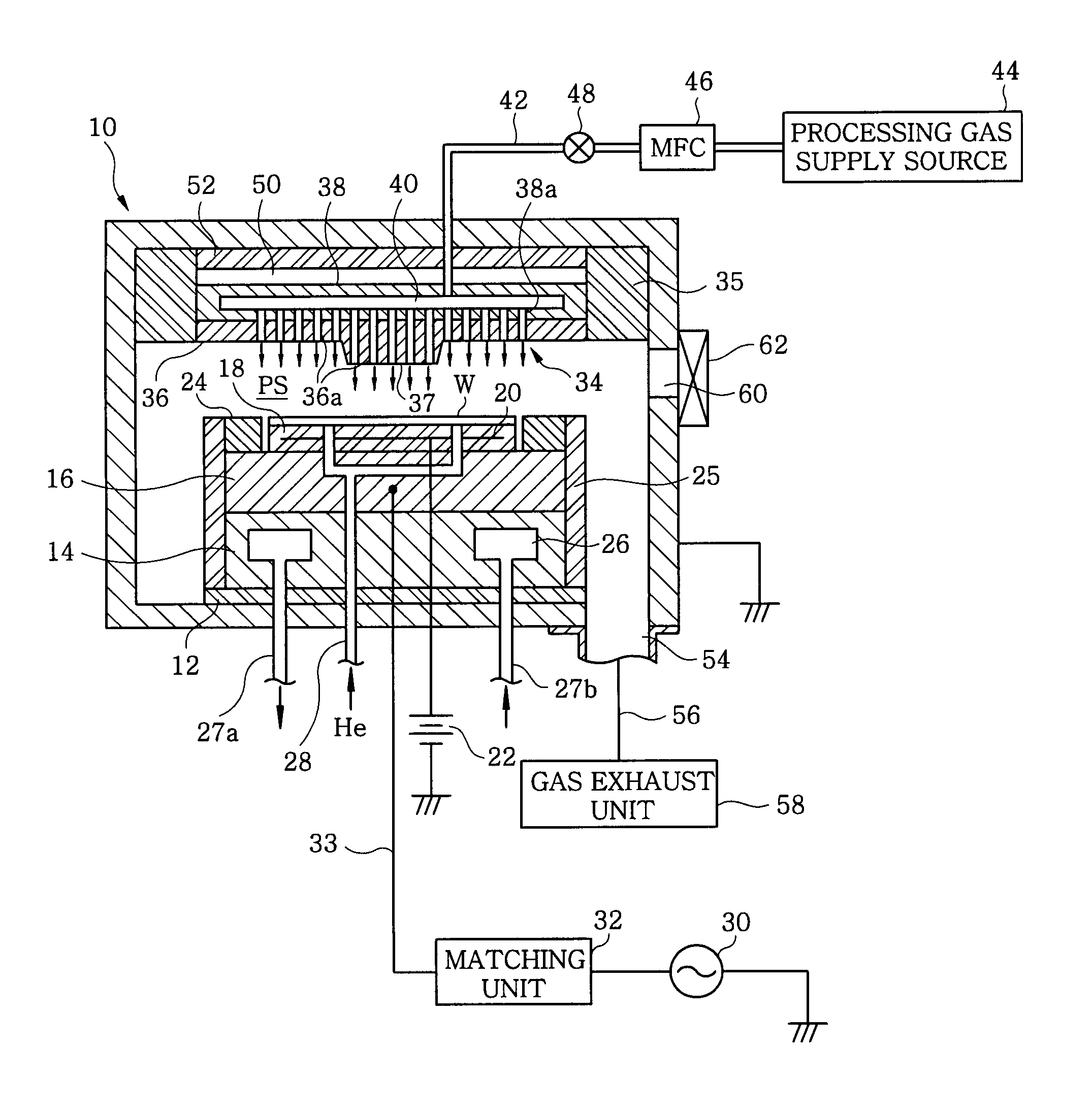
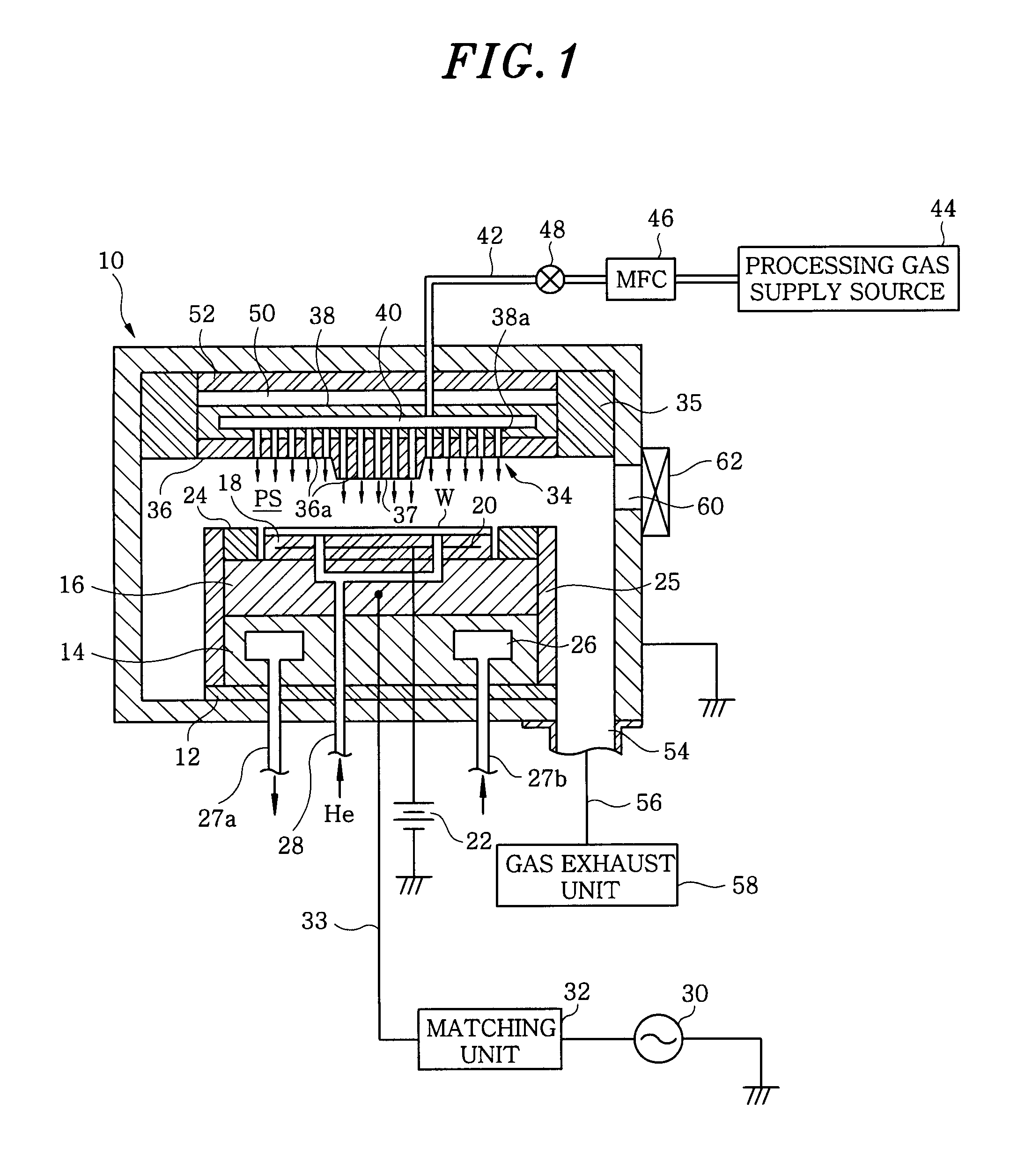
[0032]FIG. 1 illustrates a configuration of a plasma processing apparatus in accordance with an embodiment of the present invention. The plasma processing apparatus is configured as a capacitively coupled (parallel plate type) plasma processing apparatus of a cathode coupling type. The plasma processing apparatus has a cylindrical vacuum chamber (processing chamber) 10 made of, e.g., an aluminum whose surface is alumite-treated (anodically oxidized), and the chamber 10 is frame grounded.

[0033] A cylindrical susceptor support 14 is provided at a bottom portion in the chamber 10 via an insulation plate 12 made of ceramic or the like. Further, a susceptor 16 made of, e.g., aluminum, is disposed above the susceptor support 14. The susceptor 16 serves as a lower electrode and a target substrate, e.g., a semiconductor wafer W, is mounted thereon.

[0034] On the top sur...


PUM

PropertyMeasurementUnit
Capacitanceaaaaaaaaaa
Diameteraaaaaaaaaa

Abstract

A plasma processing apparatus includes a processing vessel capable of being vacuum evacuated; a first electrode installed in the processing vessel to be in a state electrically floating via an insulating member or a space; a second electrode disposed in the processing vessel to be in parallel to the first electrode with a specific interval, for supporting a target substrate thereon to face the first electrode; a processing gas supply unit for supplying a processing gas into a processing space between the first electrode, the second electrode and a sidewall of the processing vessel; and a first radio frequency power supply unit for applying a first radio frequency power to the second electrode to generate a plasma of the processing gas in the processing space. A protrusion projected toward the second electrode is formed at a central portion of the first electrode.

Description

CROSS-REFERENCE TO RELATED APPLICATIONS [0001] This document claims priority to Japanese Patent Application No. 2006-92965, filed on Mar. 30, 2006 and U.S. Provisional Application No. 60 / 791,463, filed on Apr. 13, 2006, the entire content of which are hereby incorporated by reference.FIELD OF THE INVENTION [0002] The present invention relates to a technique for performing a plasma processing on a substrate to be processed; and, more particularly, to a capacitively coupled plasma processing apparatus. BACKGROUND OF THE INVENTION [0003] In a manufacturing process of semiconductor devices or flat panel displays (FPDs), a plasma is used to perform a processing, such as etching, deposition, oxidation, sputtering or the like, so as to obtain a good reaction of a processing gas at a relatively low temperature. Conventionally, a capacitively coupled type plasma apparatus has been widely employed as a single-wafer plasma processing apparatus, especially, as a single-wafer plasma etching appa...

Claims


Application Information

Patent Timeline
IPC IPC(8): C23F1/00C23C16/00
CPCC23C16/45565C23C16/5096H01L21/31116H01J37/32091H01J37/32541C23C16/52
Inventor MATSUMOTO, NAOKIHAYAKAWA, YOSHINOBUHANAOKA, HIDETOSHIKODAMA, NORIAKIKOSHIMIZU, CHISHIOIWATA, MANABUTANAKA, SATOSHI
Owner TOKYO ELECTRON LTD
Why Eureka
Try Eureka