Polarized pulsed front-end beam source for electron microscope

a front-end beam source and electron microscope technology, applied in the field of microscopy applications, can solve the problems of ineffective and inefficient probing of some magnetic phenomena, and achieve the effect of improving performan

Inactive Publication Date: 2007-10-04
UCHICAGO ARGONNE LLC
View PDF9 Cites 12 Cited by
  • Summary
  • Abstract
  • Description
  • Claims
  • Application Information

AI Technical Summary

Benefits of technology

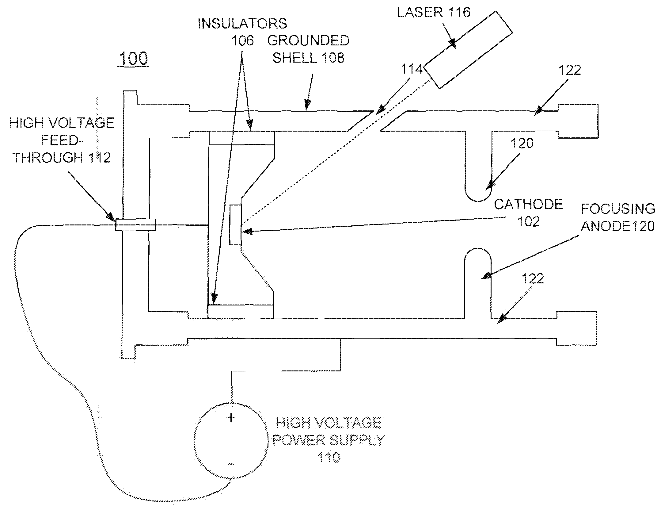
[0011]In accordance with features of the invention, by using a cathode made of gallium arsenide (GaAs) with suitable cessation of the surface, and with suitable laser light, the electrons emerge from the surface with a well-defined polarization, or spin orientation. This permits the microscope to be used to probe phenomena such as domains and domain boundaries in magnetic materials more easily than current techniques depending on post-emission sorting of the electron polarization.
[0012]In accordance with features of the invention, the use of an external laser to drive electron emission provides advantages over a conventional source where changing the beam current requires changing the emission current density on the cathode; in turn, this impacts the focusing optics along the column. With an external drive laser of the invention the current is varied without varying the emission current density simply by using a resized laser spot with proportionally scaled laser power. Since the focusing is sensitive primarily to current density, this technique allows changes in the beam current without requiring changes to the column focusing optics.
[0013]In accordance with features of the invention, gating the drive laser enables cathode emission current gating at arbitrary rates, providing improved performance over prior art arrangements.

Problems solved by technology

The electrons being randomly polarized causes inefficient and ineffective probing of some magnetic phenomena.

Method used


Image

  • Polarized pulsed front-end beam source for electron microscope
  • Polarized pulsed front-end beam source for electron microscope
  • Polarized pulsed front-end beam source for electron microscope

Examples


Embodiment Construction

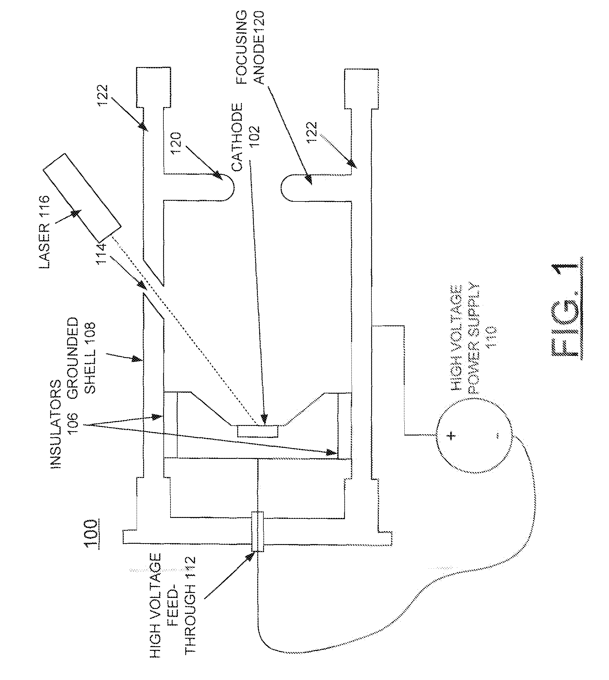
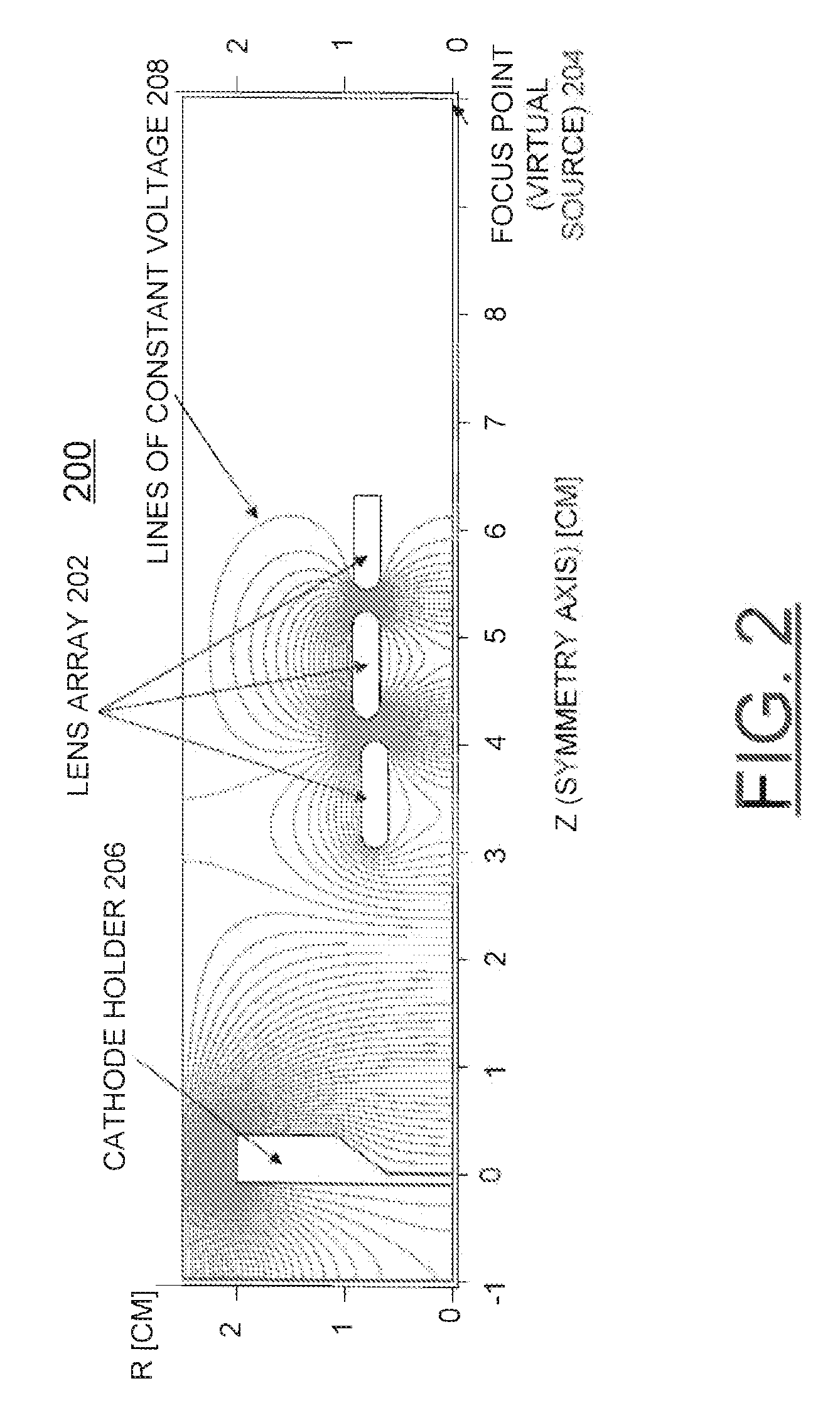
[0018]In accordance with features of the preferred embodiments, a method and an electron source are provided for generating polarized electrons for an electron microscope. The electron source is designed to replace the electron emitter in existing electron microscopes. An electron beam emitted from a photocathode-planar electron source is focused to a point source that is comparable to a thermionic or field emission cathode at the source location in the microscope column. The electrons are accelerated and focused in the existing microscope column.

[0019]In accordance with features of the invention, the polarization source assembly advantageously is designed to replace the electron emitter in existing electron microscopes. The electron beam emitted from a photocathode planar electron source is focused to a point source that is comparable to a thermionic or field emission cathode at the source location in the microscope column. The electrons are accelerated and focused in the existing ...


PUM


Abstract

A method and an electron source are provided for generating polarized electrons for an electron microscope. The electron source includes a photoemissive cathode and a low-power drive laser. The geometry of the photoemissive cathode uses a generally planar emission surface, which is imaged to approximately 1/100 its initial size via electrostatic focusing elements. The virtual emitter, or image spot, then is used as an electron source by a conventional microscope column.

Description

[0001]This application claims the benefit of U.S. Provisional Application No. 60 / 787,560, filed on Mar. 30, 2006.CONTRACTUAL ORIGIN OF THE INVENTION[0002]The United States Government has rights in this invention pursuant to Contract No. W-31-109-ENG-38 between the United States Government and The University of Chicago and / or pursuant to Contract No. DE-AC02-06CH11357 between the United States Government and UChicago Argonne, LLC representing Argonne National Laboratory.FIELD OF THE INVENTION[0003]The present invention relates to microscopy applications, and more particularly to a novel electron source for microscopy applications including electron microscopes.DESCRIPTION OF THE RELATED ART[0004]Electron microscopes require an electron source of some form. The electron source is typically either a hot cathode, such as a tungsten dispenser or LaB6, or a field emission needle cathode, for example, fine tungsten tip.[0005]In either case the electrons are emitted from the source with ran...

Claims


Application Information

Patent Timeline
Patent Type & Authority Applications(United States)
IPC IPC(8): H01J27/24
CPCH01J1/34H01J3/021H01J2237/06375H01J2237/06333H01J37/073
Inventor LEWELLEN, JOHN W.NOONAN, JOHN
Owner UCHICAGO ARGONNE LLC
Why Eureka
Try Eureka