
Light-scattering film, polarizing plate and image display

a technology of light scattering film and polarizing plate, which is applied in the direction of optical radiation measurement, instruments, measurement devices, etc., can solve the problems of low brightness, increased cost, and reduced brightness in bright rooms, so as to reduce reflection and bright room contrast, the effect of high level

Active Publication Date: 2007-10-04
FUJIFILM CORP
View PDF10 Cites 41 Cited by
  • Summary
  • Abstract
  • Description
  • Claims
  • Application Information

AI Technical Summary

Benefits of technology

[0009] One aspect of an illustrative, non-limiting embodiment of the invention is to provide a light-scattering film capable of achieving both reduction of reflection and bright-room contrast at a high level. Another aspect is to provide a polarizing plate and an image display, each using the light-scattering film.

Problems solved by technology

However, the light brownish looking of the display surface is strengthened and the contrast in a bright room (bright-room contrast) may decrease.
On the other hand, in the case of using a clear surface not imparted with antiglare property, a low refractive index layer having a low refractive index at the level enabling satisfactory reduction of reflection only by antireflection utilizing the thin-film interference of one low refractive index layer is not found at present and in the case of using thin-film interference of two or more layers differing in the refractive index, the color tint may be intensified or the cost may arise.

Method used


Image

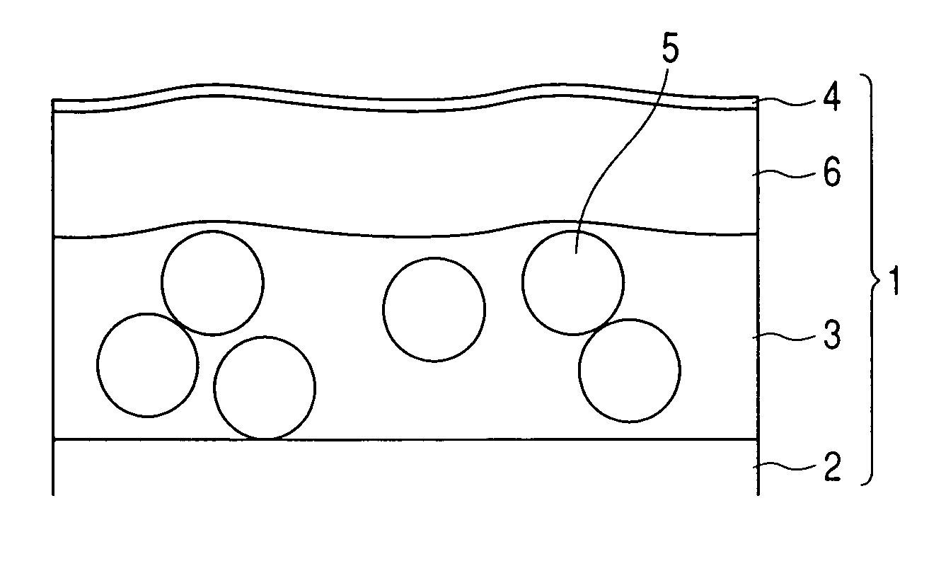
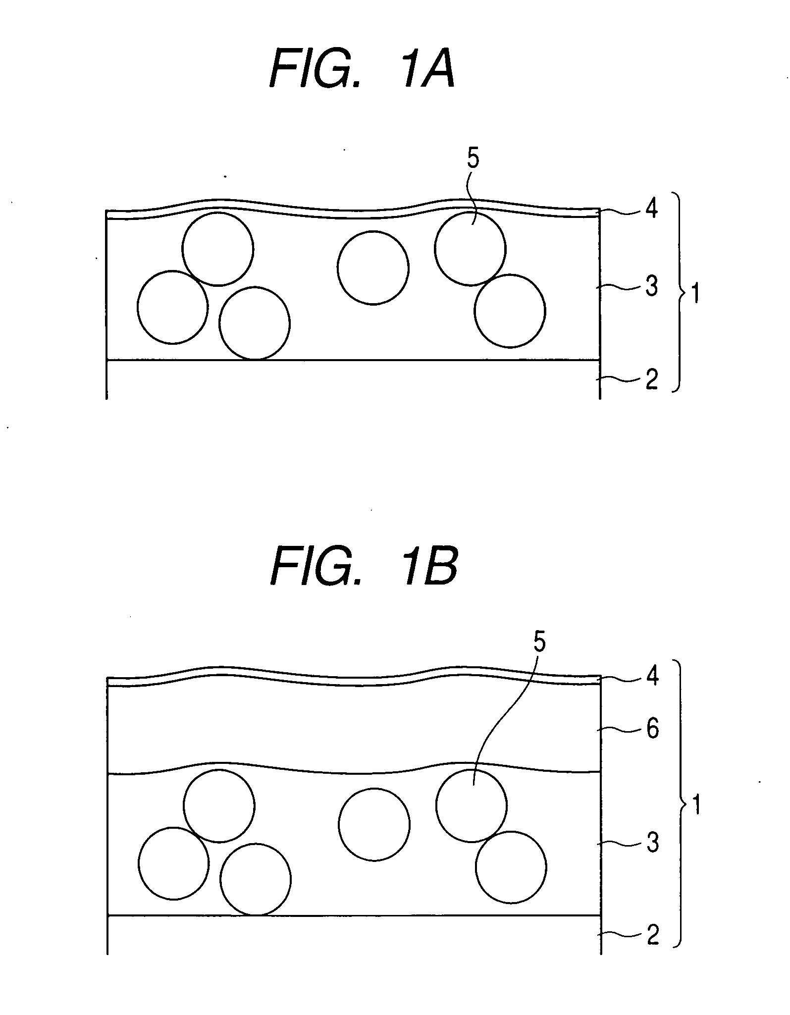
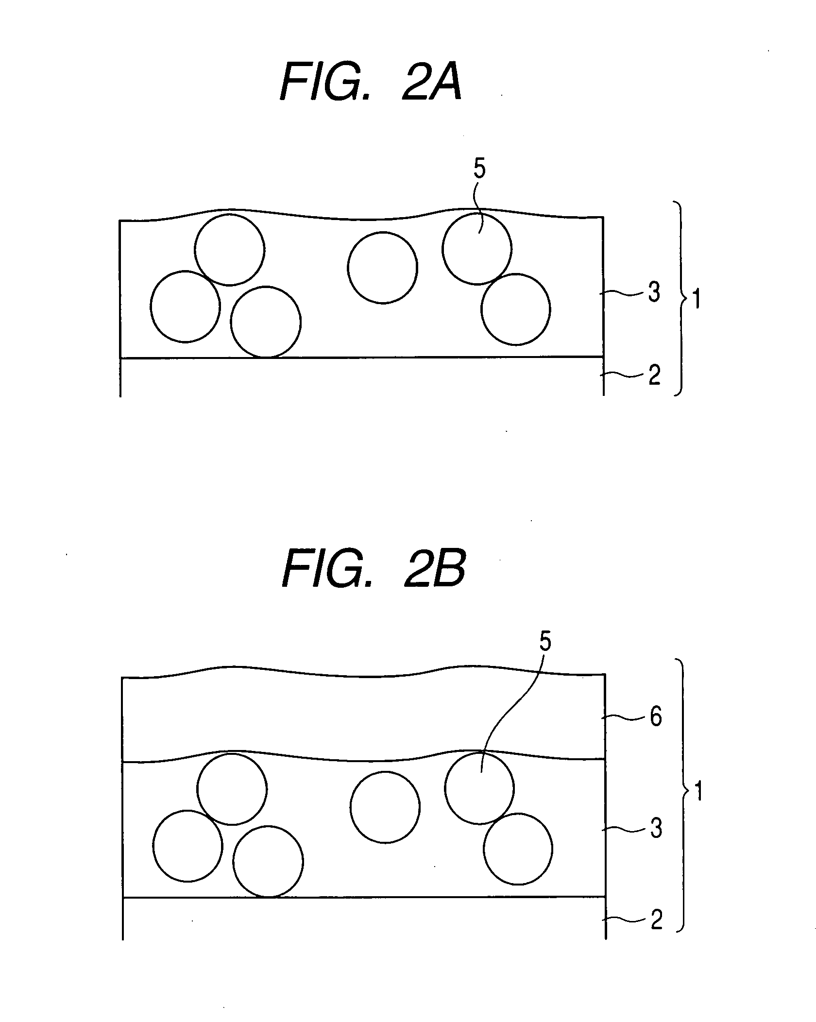
  • Light-scattering film, polarizing plate and image display
  • Light-scattering film, polarizing plate and image display
  • Light-scattering film, polarizing plate and image display

Examples


example 1

(1) Coating of Light-Scattering Layer

[0451] A 80 μm-thick triacetyl cellulose film (TAC-TD80U, produced by Fuji Photo Film Co., Ltd., refractive index: 1.49) in a roll form was unrolled as the transparent support, and Coating Solution A for Light-Scattering Layer was coated thereon by the die coating method shown in Constitution of Apparatus and Coating Conditions below and after drying at 30° C. for 15 seconds and at 90° C. for 20 seconds, irradiated with an ultraviolet ray at an irradiation dose of 90 mJ / cm2 by using an air-cooled metal halide lamp (manufactured by Eye Graphics Co., Ltd.) of 160 W / cm under nitrogen purging (for adjusting the oxygen concentration to 0.05 volume %), whereby the coated layer was cured and a 12 μm-thick light-scattering layer having antiglare property was formed. The resulting film was taken up.

Basic Conditions:

[0452] A slot die 13 where the upstream lip land length IUP is 0.5 mm, the downstream lip land length ILO is 50 μm, the length of the ope...

example 2

(Production of Polarizing Plate)

[0494] A 80 μm-thick triacetyl cellulose film (TAC-TD80U, produced by Fuji Photo Film Co., Ltd., hereinafter referred to as “TAC film”) which had been dipped in an aqueous 1.5 mol / liter NaOH solution at 55° C. for 2 minutes, neutralized and then washed with water, and the light-scattering film (Samples 1-1 to 1-24 and 1-26 to 1-33, already saponified) produced in Example 1 were bonded for protection to both surfaces of a polarizer produced by adsorbing iodine to polyvinyl alcohol and stretching the film, where by a polarizing plate was produced. Incidentally, the transparent support surface of the light-scattering film produced in Example 1 was bonded to the polarizer. These polarizing plates were designated as Samples 2-1 to 2-24 and 2-26 to 2-33, respectively.

[0495] Also, a polarizing plate was produced by using the saponified triacetyl cellulose film described above for the protective films on both surfaces and designated as Sample 2-25.

example 3

(Evaluation of Polarizing Plate)

[0496] A part of the polarizing plate on the viewing side of a 32-inch liquid crystal television, TH32LX500, manufactured by Panasonic (IPS system, dark-room contrast ratio: 750) was removed and the polarizing plate produced in Example 2 (Samples 2-1 to 2-33) was instead stacked thereto. These were designated as Samples 3-1 to 3-33, respectively. The obtained displays were evaluated on the following items. The results are shown in Tables 7 and 8.

(1) Reflection

[0497] The obtained liquid crystal television was placed in a bright room and a human face was reflected on the surface of the light-scattering film of the present invention from the 5-m distant position and the level of reflection was evaluated according to the following criteria:

[0498] A: The outline is not recognized at all.

[0499] B: The outline is scarcely recognized.

[0500] C: The outline is recognized but not annoying.

[0501] D: The outline is annoying.

(2) Bright-Room Contrast (Con...


PUM


Abstract

A light-scattering film is provided and includes a transparent support having thereon at least a light-scattering layer. When substantially parallel light is incident on a surface of the film at an incident angle of 5°, the reflectance for an angle θ in the light-receiving part measured in a plane containing the film normal line and the incident direction is R(θ), the value obtained by normalizing R(θ) by the reflectance of regular reflection is Rrel(θ), and the value calculated from the maximum variation |dRrel(θ) / dθ|max for the angle θ is a scattering coefficient A (formula 1), the reflection coefficient B (formula 2) calculated from the scattering coefficient A and the 5° specular reflectance Rs is from 2.0 to 5.0.Scattering coefficient A=1 / (10×|dRrel(θ) / dθ|max)  (Formula 1)Reflection coefficient B=2.2×log 10(Rs)−7.5×log 10(A)+5.9  (Formula 2)

Description

BACKGROUND OF THE INVENTION [0001] 1. Field of the Invention [0002] The present invention relates to a light-scattering film, a polarizing plate and an image display. [0003] 2. Description of Related Art [0004] In an image display such as CRT, plasma display panel (PDP), electroluminescent display (ELD), field emission display (FED), surface-conduction electron-emitter display (SED) and liquid crystal display (LCD), the display performance in a bright-room environment can be enhanced by preventing reflection of an image due to reflection of outside light. [0005] As for the method of preventing reflection of an image in the display surface of an image display, there are disclosed (1) a method where performance of making unclear the reflected image by surface scattering (antiglare property) is imparted to let the reflected image be less recognizable, and (2) a method where performance of reducing the amount of reflected light by providing a low refractive index layer on the outermost ...

Claims


Application Information

Patent Timeline
Patent Type & Authority Applications(United States)
IPC IPC(8): G01J1/00
CPCG02B5/0242G02B5/0268G02B5/0284G02F2202/28G02F1/133528G02F2201/38G02F2201/50G02F1/133504
Inventor INOUE, KATSUMIWATANABE, JUNASAKURA, TETSUYAWAKIZAKA, DAIKIISHIBASHI, HIDEYASUIKUHARA, ISAO
Owner FUJIFILM CORP
Learn More